
Geometric Tolerance Symbols Chart: All 13 Symbols and How to Read a Feature Control Frame
A rectangular box appears on the customer drawing holding a symbol you cannot place, a number and a letter — that is a feature control frame. This guide lists all 13 geometric tolerance symbols in one table (name, symbol, what it controls), then explains how the three compartments of the frame are filled, how the meaning changes with where the leader arrow lands, the four ways to place a datum triangle, and which compartment the Ⓜ maximum material condition modifier belongs in. To look up a symbol, go straight to the first table.
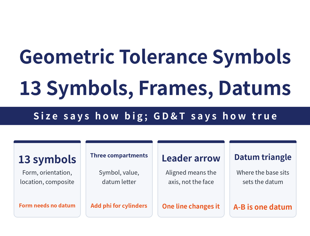
Start by separating two things: dimensional tolerance governs how big, geometric tolerance governs how true. A bore that measures 20.01 mm in every direction is fully in spec, but if the bore is tilted or sits off position, the shaft still will not go in — that is what geometric tolerance governs. For the difference between the two, see How to Read Tolerance and Fit.
1. All 13 Geometric Tolerance Symbols at a Glance
| Category | Name | Symbol | What it controls |
|---|---|---|---|
| Form | Straightness | ⏤ | How straight a line on a surface, or the centre axis of a body of revolution, is |
| Form | Flatness | ⏥ | How flat a single surface is |
| Form | Roundness | ○ | How round a cylinder, cone or sphere is |
| Form | Cylindricity | ⌍ | Roundness, straightness and parallelism of a cylindrical surface combined |
| Form | Profile of a line | ⌒ | The profile shape at every point along a curved line |
| Form | Profile of a surface | ⌓ | The profile shape at every point over a curved surface |
| Orientation | Parallelism | ∥ | How parallel a line or plane is to the datum |
| Orientation | Perpendicularity | ⊥ | How perpendicular a line or plane is to the datum |
| Orientation | Angularity | ∠ | The error in holding a line or plane at a specified angle to the datum |
| Location | Position | ⊕ | How far a feature departs from its true position |
| Location | Concentricity | ◎ | How far the centre of a circle or cylinder departs from the datum centre |
| Location | Symmetry | ⌧ | How far a feature departs from the true position of the symmetry datum |
| Composite | Runout | ↗ | The maximum variation permitted during one full rotation about the datum axis |
2. How the Four Categories Split: Whether the Frame Carries a Datum Letter
The four categories divide like this: form looks only at the feature itself and needs no datum; orientation and location are both relationships between two features, so a datum is mandatory; runout is the composite item, measured as the largest variation over one full turn. Whether a datum letter appears in the frame follows directly from that split.
The symbols have a specified size of their own: the size and line thickness of the feature control frame and of the symbols are proportional to the height of the dimension figures. When the drawing is scaled, the symbols scale with it — they are not a fixed size.
3. The Three Compartments of a Feature Control Frame
A feature control frame is a rectangle drawn in a thin continuous line, about twice the height of the dimension figures, divided into compartments. Three things are entered, from left to right:
| Order | What goes in | Watch for |
|---|---|---|
| ① | The geometric tolerance symbol | One of the 13 in the table above |
| ② | The tolerance value | When the tolerance zone is circular or cylindrical, the value is prefixed with φ |
| ③ | The datum letter | Present only when a datum is required; form items have no such compartment |
So ⌍ 0.02 A reads as "cylindricity tolerance 0.02 with respect to datum A", and ⊕ φ0.1 reads as "position tolerance, with a tolerance zone that is a circle of diameter 0.1". Whether that φ is there matters — it decides whether the tolerance zone is a circle (or cylinder) or the distance between two parallel lines.
4. Where the Leader Arrow Lands Changes What Is Controlled
With the same frame, a different landing point for the leader arrow means a completely different controlled feature. This is the single easiest thing to misread on a drawing:
| The arrow lands on | What is controlled |
|---|---|
| An outline or its extension line, not aligned with the dimension line | That outline or surface itself (not permitted with maximum material condition) |
| An outline or its extension line, aligned with the dimension line | The centre axis of the feature that dimension applies to; the arrow may share the dimension line |
| A centre line | All geometric features taking that centre line as their axis |
It all turns on one thing: alignment with the dimension line. Aligned, and the centre axis is controlled; not aligned, and the surface is. Measurement and acceptance differ completely between the two.
5. Four Ways to Place the Datum Triangle
A datum is marked with a filled or open equilateral triangle, and where the base of the triangle sits decides what the datum is:
| Position of the base | The datum is |
|---|---|
| On an outline or its extension line, not aligned with the dimension line | That outline or surface itself |
| On a centre line | The common centre axis of all features taking that centre line as their axis |
| Aligned with a dimension line | The centre line of the feature that dimension applies to; the triangle may replace the arrowhead at the end of the dimension line |
| Far away from the frame | Identified by a boxed capital letter, with the letter entered in the rightmost compartment of the frame |
When there is more than one datum: letters with no order of precedence take no hyphen between them; when two datum planes or datum lines combine into a single datum, they are joined with a short hyphen and written A-B. That hyphen changes the meaning substantially.
6. What a Notation Like 0.1/100 Means
The tolerance value is sometimes not a single number but a combination separated by a slash. That is a restricted-length tolerance:
| Notation | Meaning |
|---|---|
0.1/100 | Within any 100 units of length in any direction, the error must not exceed 0.1 unit |
0.1/0.05/100 | Tolerance over the whole feature is 0.1, with the added restriction that within any 100 units of length in any direction it must not exceed 0.05 unit |
The point of writing it this way is to stop the error piling up in one short stretch. Spreading 0.1 mm evenly across a surface one metre long is one thing; concentrating all of it inside a single 100 mm is another, and the second one causes trouble at assembly.
7. Which Compartment Ⓜ Maximum Material Condition Goes In
Maximum material condition (MMC) is the limit of size at which the part contains the most material: the MMC of a shaft is its maximum limit of size, and the MMC of a hole is its minimum limit of size. Two mating parts each at MMC is the least favourable extreme.
The principle behind it: when the actual size moves away from the maximum material limit (the hole larger than its minimum, the shaft smaller than its maximum), the geometric tolerance may exceed its stated value without affecting function or assembly. In other words, looser size buys looser position — that is room worth negotiating at quotation stage, not a shortcut.
There are two places the modifier can be added, and they mean different things: applied to the tolerance value, Ⓜ goes after the tolerance value; applied to the datum feature, Ⓜ goes after the datum letter. The three frame arrangements checked against the source are ◎ φ0.04 Ⓜ, ◎ φ0.04 A Ⓜ and ◎ φ0.04 Ⓜ A Ⓜ — all three control different things, so count carefully which compartment each Ⓜ sits in.
8. Why 13 Symbols and Not 17 Items
The list of geometric tolerance terms runs to 17 items, but there are only 13 symbols, and the two numbers not matching is normal. The difference is: maximum material condition (symbol Ⓜ, a modifier rather than a tolerance item), plus the three definitional entries — geometric tolerance, tolerance zone and datum feature. Those are definitions of terms, so they never had a frame symbol to begin with. There is no need to look for those four in the chart.
9. How to Set Tolerance Values, and What the Symbols Here Are Based On
What value to set for the tolerance itself is a separate question. For dimensional tolerance values, see Hole Tolerance Chart and Shaft Tolerance Chart. For geometric tolerance values there is no general table of recommendations; they are set from functional requirements every time. Do not tighten them for insurance — the tighter the tolerance, the faster machining and inspection costs climb.
The symbols used here were reconstructed by reading the symbol table in the original teaching material, and that material does not state which edition of which standard it follows, so no standard number is cited in this article. For production drawings and acceptance, follow the original text of the drafting standard your company has adopted.
FAQ
Q: What is the difference between dimensional tolerance and geometric tolerance?
Dimensional tolerance governs how big, geometric tolerance governs how true. A bore can measure in spec in every direction, but if it is tilted or off position the shaft still will not go in, and that is geometric tolerance territory. The two are marked separately on the drawing: dimensional tolerance next to the dimension figures, geometric tolerance inside a rectangular frame.
Q: Does it matter whether the number in the frame is prefixed with φ?
It matters a great deal. With φ, the tolerance zone is a circle or a cylinder — φ0.1 is a cylindrical space 0.1 in diameter. Without φ, the tolerance zone is the distance between two parallel lines or two parallel planes. The same number allows a different range depending on the prefix, and it is measured differently too.
Q: Do datum letters written A B mean the same as A-B?
No. Letters with no hyphen between them mean several datums with no order of precedence. Joined with a short hyphen as A-B, they mean a single datum formed by combining two datum planes or datum lines. Do not overlook the hyphen when reading a drawing.
Q: What geometric tolerance is typical, and is there a table of recommended values?
There is no general table of recommended values, and there should not be — geometric tolerance is set from functional requirements. Ordinary parts mostly land in the 0.01 to 0.3 mm range, but that is a sense of magnitude, not a recommendation. The tighter it is, the faster machining and inspection costs climb, and the part is no more usable for it. The right approach is to ask what goes wrong if this face is not true, then work back to how true it needs to be.









