
What Is Geometric Tolerance: The 17 Terms, the Tolerance Zone and Maximum Material Condition
The size is inside the tolerance band and the parts still will not go together — geometric tolerance is what you look at next. This guide explains what geometric tolerance actually governs (a tolerance zone, not a single number), the four things a tolerance zone can be, how the 17 terms split into 6 form tolerances and 7 location tolerances, why there are 17 terms but only 13 symbols, and why the Ⓜ maximum material condition modifier lets a geometric tolerance open up.
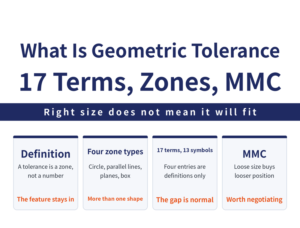
The bore is machined to H7, it measures in spec in every direction, and the shaft still will not go in. That sentence in How to Read Tolerance and Fit — "the size being right does not mean it will assemble, and this is the pit beginners fall into most often" — is about exactly this, and this article is the way out of that pit. Dimensional tolerance governs how big, geometric tolerance governs how true.
1. Geometric Tolerance Governs a Zone, Not a Number
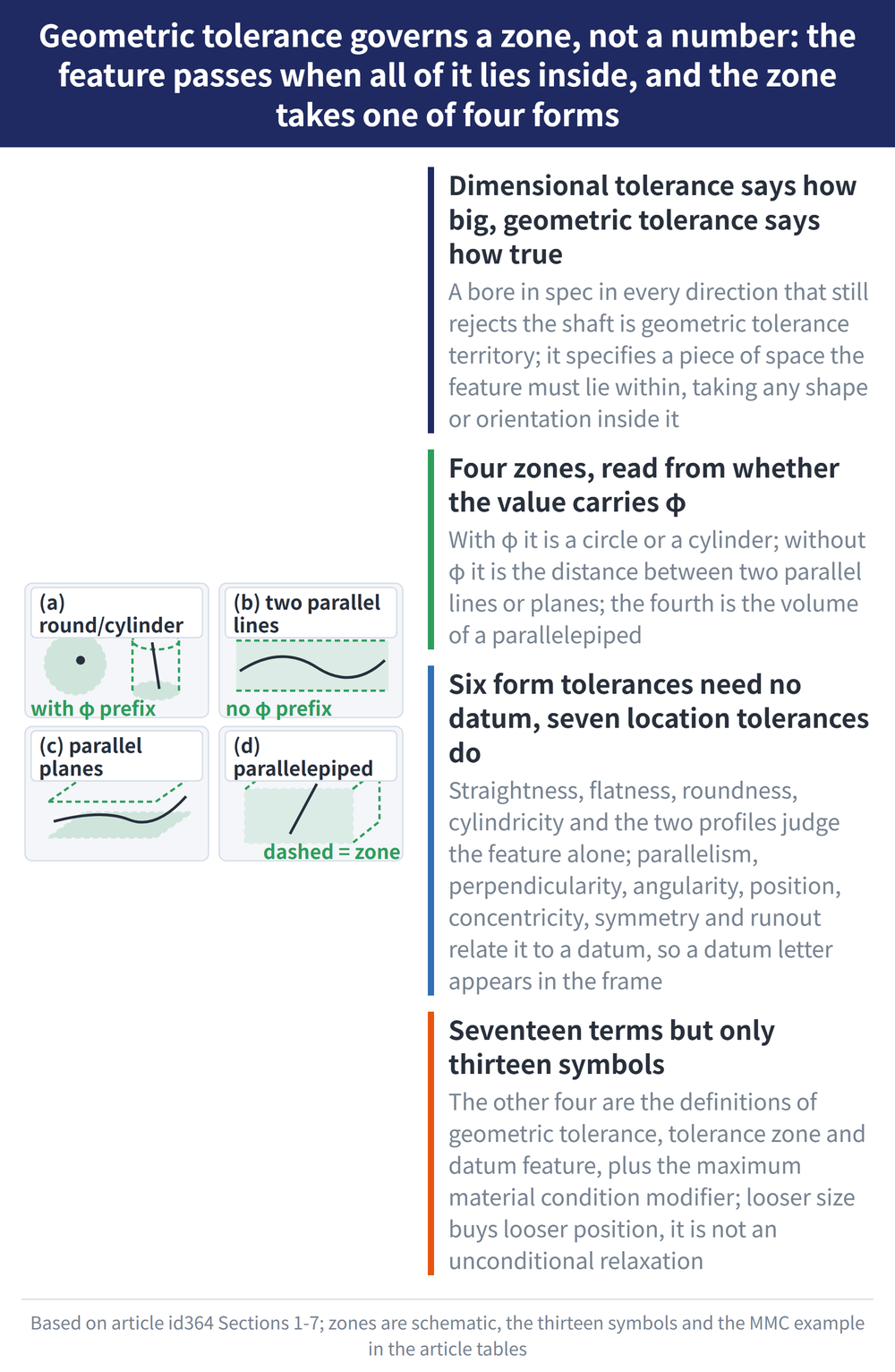
The definition: geometric tolerance is the tolerance on the form of a geometric feature, or on the position it occupies — that is, it specifies a tolerance zone, and the feature or its position must lie within that zone.
So a geometric tolerance is not a single acceptance figure, it is a piece of space. The feature is in spec as long as the whole of it falls inside that space, and within the zone it may take any shape or orientation; if shape or orientation must be restricted as well, that has to be noted separately.
Geometric tolerance therefore covers two families: form tolerance, which looks at how true a single feature is on its own, and location tolerance, which looks at the relationship between two features.
2. The Four Things a Tolerance Zone Can Be
Depending on the nature of the feature and on how the tolerance is indicated, the zone may be any of these four:
| Case | What the tolerance zone is |
|---|---|
| (a) | The area inside a circle, or the volume of a cylinder |
| (b) | The space between two parallel curves or two parallel straight lines |
| (c) | The space between two parallel curved surfaces or two parallel planes |
| (d) | The volume of a parallelepiped |
On the drawing, which case applies is read from whether the tolerance value is prefixed with φ: with φ it is a circle or a cylinder, without φ it is the distance between two parallel lines or two parallel planes. For how to read the frame itself, see Geometric Tolerance Symbols Chart.
3. The Six Form Tolerances: The Feature on Its Own
| Name | Symbol | What it controls |
|---|---|---|
| Straightness tolerance | ⏤ | The straightness of a line on a surface, or of the centre axis of a body of revolution |
| Flatness tolerance | ⏥ | The flatness of a single surface |
| Roundness tolerance | ○ | The roundness of a cylinder, cone or sphere |
| Cylindricity tolerance | ⌍ | The combined roundness, straightness and parallelism of a cylindrical surface |
| Profile of a line tolerance | ⌒ | The profile shape at every point along a curved line |
| Profile of a surface tolerance | ⌓ | The profile shape at every point over a curved surface |
What these six have in common is that no datum is needed: what is measured is whether this surface, this line, this circle is true in itself, not how it compares with another feature. Their frames therefore carry no datum letter compartment.
4. The Seven Location Tolerances: Relationships Between Two Features
| Group | Name | Symbol | What it controls |
|---|---|---|---|
| Orientation | Parallelism tolerance | ∥ | How parallel a line or plane is to the datum |
| Orientation | Perpendicularity tolerance | ⊥ | How perpendicular a line or plane is to the datum |
| Orientation | Angularity tolerance | ∠ | The error in holding a line or plane at a specified angle to the datum |
| Position | Position tolerance | ⊕ | How far a geometric feature departs from its true position |
| Position | Concentricity tolerance | ◎ | How far the centre of a circle or cylinder departs from the centre of its datum feature |
| Position | Symmetry tolerance | ⌧ | How far a feature departs from the true position of its symmetry datum feature |
| Separate item | Runout tolerance | ↗ | The maximum variation permitted at any position as the part makes one full rotation about the datum axis |
All seven require a datum, so a datum letter appears in the rightmost compartment of the frame. Whether runout belongs to the orientation or the position group could not be determined, because the classification table image in the original teaching material is damaged; it is listed here as a separate item, as the source material has it.
5. Seventeen Terms, Only Thirteen Symbols
The two sections above come to 13 items, each with its own frame symbol. But the list of geometric tolerance terms runs to 17. The four that make up the difference are these:
| Term | What it actually is |
|---|---|
| Geometric tolerance | The umbrella definition: the tolerance on the form of a geometric feature or on its position, covering form tolerance and location tolerance |
| Geometric tolerance zone | The piece of space the feature must fall inside; the four cases are in section 2 |
| Datum feature | A datum plane or a datum line, which every kind of geometric tolerance is referred to |
| Maximum material condition | The modifier Ⓜ, added after the tolerance value or after the datum letter; not a tolerance item in its own right |
The first three are definitions of terms, so they never had a frame symbol; the fourth is a modifier. There is no need to look for these four in a symbol chart.
6. What Maximum Material Condition (MMC) Is
Maximum material condition (MMC) is the limit of size at which the part contains the most material. The direction is opposite for the two mating features, which is the part most often remembered backwards:
| Feature | Its maximum material condition is | Example in the source material |
|---|---|---|
| Shaft | The maximum limit of size of the shaft | φ27 |
| Hole | The minimum limit of size of the hole | φ22 |
The logic is straightforward: the thicker the shaft the more material it has, and the smaller the hole the more material is left around it. When two mating parts are each at their own maximum material condition, the two exist at the least favourable extreme — the thickest shaft against the smallest hole, the hardest combination to assemble.
7. Looser Size Buys Looser Position: The MMC Principle
The principle: when the actual size of both mating parts, or of one of them, moves away from its maximum material limit (the hole larger than its minimum, the shaft smaller than its maximum), the geometric tolerance may exceed its originally stated range without affecting function or assembly.
For anyone quoting a job, the practical meaning is this: if the size is held looser than the worst case, the permissible positional error gains an extra allowance, and there is no need to squeeze the position tolerance for insurance. That is room that can be negotiated on the drawing, not a shortcut.
There are two places the modifier goes, and they mean different things: applied to the tolerance value, Ⓜ is added after the tolerance value; applied to the datum feature, Ⓜ is added after the datum letter. For choosing how tight or loose the hole-and-shaft fit itself should be, see Tolerance Grades and Fits Explained.
8. So What Value Should a Geometric Tolerance Be
There is no general table of recommended values. Geometric tolerance is always set from functional requirements: first ask what goes wrong if this face is not true, then work back to how true it needs to be.
If a sense of magnitude helps: geometric tolerances on ordinary parts mostly land in the 0.01 to 0.3 mm range — but that is a magnitude, not a recommendation, and the value still has to be set from functional requirements, so those two numbers must not simply be written onto a drawing. The tighter the tolerance, the faster machining and inspection costs climb, and the part is no more usable for it.
Dimensional tolerance values do have lookup tables of their own; see Hole Tolerance Chart. The definitions and classification here are compiled from the original teaching material, and that material does not state which edition of which standard it follows, so no standard number is cited; for production drawings and acceptance, follow the original text of the drafting standard your company has adopted.
Frequently Asked Questions (FAQ)
Q: What is the difference between geometric tolerance and dimensional tolerance?
Dimensional tolerance governs how big, geometric tolerance governs how true. Dimensional tolerance gives a range of values; geometric tolerance gives a tolerance zone that the whole feature must lie within. A bore can measure in spec in every direction, but if it is tilted or off position the shaft still will not go in, and that is geometric tolerance territory.
Q: Why are there 17 terms but only 13 symbols?
Because 4 of the 17 are not tolerance items. The 6 form tolerances plus the 7 location tolerances make the 13 that carry a frame symbol; geometric tolerance, geometric tolerance zone and datum feature are definitions of terms, and maximum material condition is the modifier Ⓜ. There is no need to look for these four in a symbol chart.
Q: Does adding maximum material condition mean the tolerance can be opened up?
Only on condition that the actual size moves away from the maximum material limit. When the hole is made larger than its minimum limit, or the shaft smaller than its maximum limit, the geometric tolerance may exceed its stated range without affecting function or assembly. Looser size buys looser position; it is not an unconditional relaxation.
Q: What geometric tolerance is typical, and is there a table of recommended values?
There is no general table of recommended values, and there should not be. Ordinary parts mostly land in the 0.01 to 0.3 mm range, but that is a sense of magnitude, not a recommendation, and the value is always set from functional requirements. The tighter it is, the faster machining and inspection costs climb, and the part is no more usable for it.









