
Toolpath Planning for Overhung Workpieces and Small Bores: Stock Removal Passes, Zero-Point Drift and Boring Bar Geometry Limits
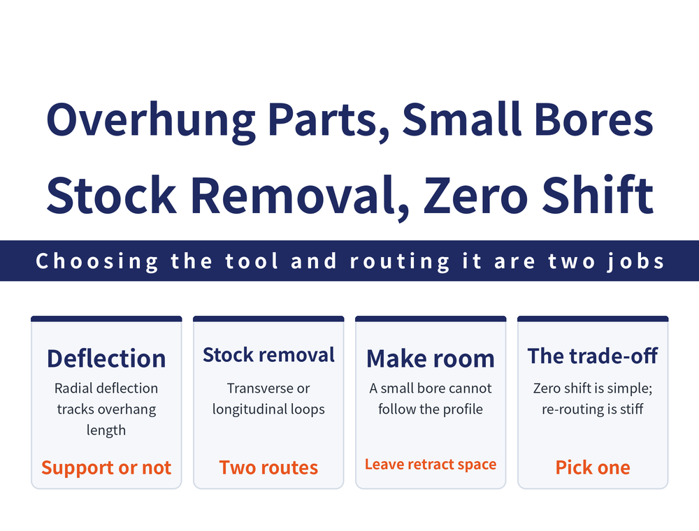
When the workpiece hangs far out of the chuck and the bore is both deep and narrow, the toolpath cannot simply follow the part profile. This guide starts from the part structure: why radial deflection of the workpiece is proportional to overhang length, the two stock removal loops used to rough an overhung stepped shaft, why a small bore must have retract space planned in first, the four geometric constraints that cavity space imposes on the boring bar, and the trade-off between zero-point drift and a purpose-designed contour path on a stepped curved deep bore.
1. The Boundary First: This Guide Is About the Toolpath the Part Forces on You
The same shop-floor problem can be approached from two ends. One end is which tool to choose — tool holder parameters, tool overhang ratios, the principles of fine boring. For that end see Fine Boring and Tool Overhang: Single-Edge Fine Boring, Holder Parameters and Five Principles; this guide does not repeat it.
The other end is the part structure: the workpiece itself hangs far out, the cavity itself is narrow and wavy, and so the toolpath can only run one way and the bar can only be so thick. This guide takes the second end, and deals with the compromise between path and size rather than with tool selection.
For the general rules of path planning (definition, four principles, lead-in and retract methods) see How to Plan a Turning Feed Path; this guide covers only these two structural special cases.
2. Why Workpiece Overhang Forces the Toolpath to Change
Most turned parts are machined in an overhung condition. Overhung work generally comes in two forms: tail end unsupported, and tail end supported by a centre. The centre is there precisely to stop rigidity falling away when the workpiece hangs too far out, which lets cutting induce substantial radial deflection of the part.
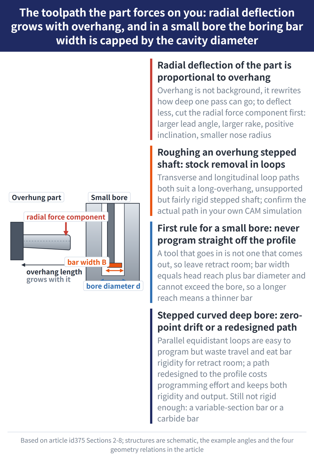
The governing statement is this: radial deflection of the workpiece during cutting is proportional to overhang length. Appropriate measures therefore have to be taken during machining to reduce or compensate the radial deflection of an overhung workpiece, and so to reduce or remove its effect on accuracy.
What that means for the toolpath is that overhang length is not background information. It directly rewrites how deep a pass can be and how the path may run.
3. To Cut Deflection, First Cut the Radial Cutting Force Component
During machining, the smaller the radial cutting force component, the smaller the radial deflection of the workpiece. All four directions below help reduce the radial force component, and with it the radial bending deflection of the part:
| Measure | How far the guidance goes |
|---|---|
| Increase the tool lead angle | 93° is the example value |
| Choose a larger tool rake angle | 15°–30° is the example range |
| Use a positive inclination angle | Direction only, no angle value given |
| Reduce the nose radius | Direction only, no quantified threshold |
93° and 15°–30° are example values, not general specifications; the other two items carry only a qualitative direction with no quantified threshold. Base the actual choice on the tool catalogue and on trial cuts.
4. Roughing an Overhung Stepped Shaft: Two Stock Removal Paths
For a stepped shaft that hangs a long way out with the tail end unsupported, but which is itself reasonably rigid and deflects little radially, roughing from bar stock has a lot of stock to remove and is generally programmed as a loop.
There are two ways to loop the stock off: transverse loop stock removal and longitudinal loop stock removal.
| Path type | Stated precondition |
|---|---|
| Transverse loop stock removal | Long overhang, tail unsupported, reasonably rigid stepped shaft with small radial deflection |
| Longitudinal loop stock removal | As above; only a qualitative contrast of the two shapes |
The difference between the two path shapes is graphical, and text alone cannot fully reconstruct the path geometry. Confirm the actual shape against the original figures or by simulating in your own CAM system.
5. The First Rule for Small Bores: Do Not Program Straight Off the Profile
Some sleeve-type parts are small in diameter, long, and have a strongly undulating internal surface, so cutting space is tight and tool movement is difficult. When setting a toolpath for this kind of part, you cannot program purely to the part profile; retract space has to be left.
This runs against the instinct built up on external turning. On an outside diameter the tool can hug the profile; inside a bore it cannot. Getting the tool in is not the same as getting it out.
Then comes the dilemma of the bar itself. Where the internal cavity is deep and long, the boring bar should be as thick as possible to raise its rigidity; but the strongly undulating internal contour limits how far bar size can be increased. Rigidity wants it thick, access wants it thin — and in the next section that conflict becomes four expressions.
6. Four Geometric Constraints the Cavity Puts on the Boring Bar
Working from the internal cavity space, the parts of the boring tool must meet the following requirements. D and d are dimensions related to the cavity outer and inner diameters, A is the head projection length, B is the boring tool width and d1 is the boring bar diameter:
Head projection length A ≥ (D−d)/2 | Boring tool width B = A + d1, and B ≤ d | Boring bar diameter d1 = B − A
The four expressions are transcribed as written, unmodified. The actual geometric location of each symbol has to be confirmed against the original figure; no values have been substituted or verified here, and the expressions have not been generalised into a universal formula. When actually sizing a boring bar, work from the dimensioned cavity drawing and the tool maker's specification tables.
The way to read the set is this: B ≤ d is the ceiling. Boring tool width is capped by the cavity bore, and width equals head projection plus bar diameter, so the further the head has to reach, the thinner the bar must become. That is exactly how rigidity gets eaten away.
7. Stepped Curved Deep Bores: Zero-Point Drift or a Redesigned Path
Machining an internal contour with strong undulation follows the same logic as the stepped shaft: loop the stock off first. There are two choices of path, and they form a very typical trade-off.
| Path | Benefit | Cost |
|---|---|---|
| Zero-point drift: loop the stock off on fully parallel, equally spaced passes | Simple to program | Air moves in the middle of the pass; the boring tool needs a lot of retract space, so the bar has to be made smaller, which conflicts with rigidity |
| A tool path redesigned around the internal contour shape | Ensures the job completes smoothly, and machining efficiency also improves | Adds programming difficulty and workload |
In one line: save the programming effort and you pay in bar rigidity and air-cutting time; spend the programming effort and you keep both rigidity and efficiency. It is a direct case of trading path complexity for rigidity and efficiency.
8. Where the Structure Comes From, and Two Rigidity Measures
A stepped curved deep bore resembles the tight-space structure, differing in that the internal curved surface tapers inward from the face, with a large diameter difference between the large and small ends — a round bottle mould cavity is typical. The main machining problems fall in three places: bar rigidity, a sensible head projection length, and tool cutting angles.
If rigidity is still short after the path has been reworked, there are two routes to stiffen the bar: design a variable-section bar that follows the cavity curve (alloy steel with hardening is a suitable material); and, if that still does not meet requirements, move to a tungsten carbide bar, which costs relatively more.
Thin-wall parts follow a different logic for operation sequence and deflection control — see How to Sequence Operations for Thin-Wall Turning. For cutting conditions and the related formulas see Turning Machining Formulas.
For the full reading guide on this topic, see Turning Toolpaths: The Complete Guide.
Frequently Asked Questions (FAQ)
Q: How much worse does deflection get when the workpiece hangs out further?
This is a qualitative relationship: radial deflection of the workpiece during cutting is proportional to overhang length. Double the overhang and the radial deflection rises with it, which is not a marginal difference. The actual figures depend on material, diameter and cutting conditions; there is no general conversion, so rely on trial cuts and measurement.
Q: Transverse or longitudinal loop for stock removal, which should I pick?
Both apply to roughing a stepped shaft that hangs a long way out with the tail unsupported but is itself reasonably rigid. There is no ranking or quantified selection threshold between the two path shapes in the text, so compare pass length and air moves in your own CAM simulation before deciding.
Q: What does zero-point drift mean?
It refers to removing stock from a strongly undulating internal contour on fully parallel, equally spaced looping passes. The advantage is that it is simple to program. The drawbacks are air moves in the middle of the pass and the large retract space the boring tool needs, which forces a thinner boring bar and conflicts with the rigidity requirement.
Q: How does this differ from the fine boring and tool overhang guide?
The viewpoint differs. The fine boring guide takes the tool viewpoint: how to choose the tool, holder parameters and the principles of fine boring. This guide takes the part viewpoint: how workpiece overhang and a tight cavity, as part structures, constrain the toolpath and the boring bar size. The two are complementary, not overlapping.









