
Tool Holder Balance: G2.5 / G6.3 and High RPM
A tool holder's dynamic balance sets the vibration, runout and spindle life in high-rpm machining. The faster it spins, the more any small unbalance is amplified by centrifugal force (which rises with the square of speed), degrading finish, shortening tool life and wearing spindle bearings. Balance quality is expressed as a "G value" (per ISO 21940)—the smaller the number, the better the balance—commonly G6.3 (general) and G2.5 (high-speed, high-precision); the higher the rpm, the stricter the grade needed. This guide explains why balance matters, the G value and residual unbalance, recommended grades by rpm, and how to achieve good tool holder balance.
1. Why a tool holder needs dynamic balance
Any slight asymmetry in a holder's mass distribution (unbalance) produces centrifugal force when it spins fast, throwing the tool tip off-centre. The key point is that centrifugal force rises with the square of speed—double the rpm and the force is four times greater. So an unbalance you can ignore at low speed becomes clear vibration and runout at high rpm, with four consequences: worse surface finish, shorter tool life, faster spindle-bearing wear and unstable accuracy. The higher the rpm, the less you can skip balancing.
2. What is the G value (balance quality grade)
Balance quality is given as a "G value" (per ISO 21940, formerly ISO 1940). It represents the permissible residual unbalance—the smaller the number, the better the balance. Common grades:
| Balance grade | Position | Typical use |
|---|---|---|
| G6.3 | General purpose | General-speed machining |
| G2.5 | High-speed, high-precision | Common requirement for high-rpm holders |
| G1.0 | Stricter | Ultra-high-speed, precision |
| G0.4 | Very strict | Ultra-precision / ultra-high-speed spindles |
The permissible residual unbalance (U) can be estimated with a reference formula: U (g·mm) ≈ 9549 × G × m ÷ n (m = holder mass in kg, n = rpm). The formula shows that for the same G grade, the higher the rpm n, the smaller the permissible unbalance U—which is why high-speed holders demand a stricter grade. Actual values follow a balancing-machine measurement.
3. Recommended balance grade by rpm
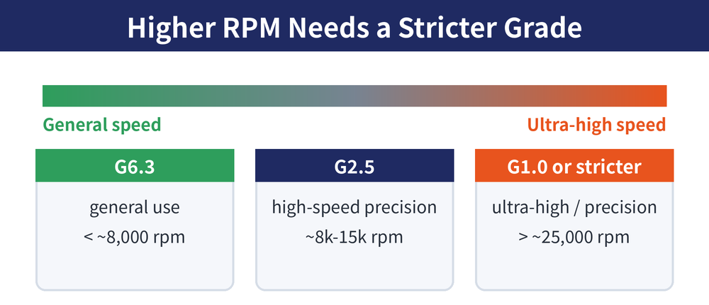
The higher the rpm, the stricter the grade needed. Common reference guidance:
| Spindle rpm (ref.) | Suggested balance grade |
|---|---|
| approx. < 8,000 rpm | G6.3 usually adequate |
| approx. 8,000–15,000 rpm | G2.5 recommended |
| approx. 15,000–25,000 rpm | G2.5–G1.0 |
| approx. > 25,000 rpm | G1.0 or stricter |
The table is rough guidance; actual needs vary with holder mass, overhang, spindle spec and the job—always follow a real balancing measurement and the spindle maker's advice.
4. What affects balance and how to improve it
| Factor | Notes and countermeasure |
|---|---|
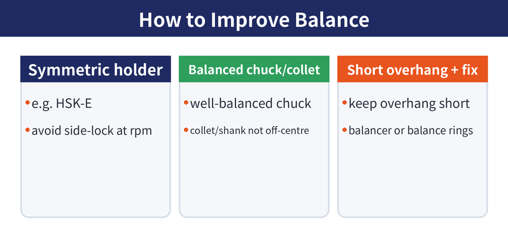
| Holder symmetry | Symmetric holders (e.g. HSK-E) balance well; side-lock is offset by its screw and is unfavourable at high rpm—avoid it there |
| Chuck and collet | Use a well-balanced chuck; an off-centre collet, nut or shank also ruins overall balance |
| Overhang | The longer the overhang and the more mass sits outboard, the greater the unbalance effect—keep it short where rigidity allows |
| Balance correction | Measure and correct on a balancing machine, or choose a holder with adjustable balance rings / screws |
| Balance as an assembly | Balance is of the whole "holder + chuck + collet + tool"; changing the tool or overhang changes it, so treat it as a set |
Further reading: BT vs HSK Spindle Taper, Face Milling Surface Finish, End Mill Length vs Deflection.
FAQ
Q: What is the difference between G2.5 and G6.3?
Both are ISO 21940 balance-quality grades; a smaller number is better balanced. G6.3 is general purpose; G2.5 is stricter and is the common requirement for high-rpm, high-precision holders. At the same rpm and mass, G2.5 permits about half the residual unbalance of G6.3, so high-speed work usually calls for G2.5 or stricter.
Q: Why is balancing essential at high rpm?
Because centrifugal force rises with the square of speed—double the rpm and it becomes four times greater. An unbalance you could ignore at low speed is amplified into clear vibration and runout at high rpm, degrading finish, shortening tool life and accelerating spindle-bearing wear. So the higher the rpm, the stricter the balance requirement.
Q: How do I achieve good tool holder balance?
Prefer a symmetric holder (e.g. HSK-E) and a well-balanced chuck, keep the overhang short, and make sure the collet and shank are not seated off-centre; avoid offset side-lock for high-speed work. Correct on a balancing machine if needed, or use a holder with adjustable balance rings/screws. Remember balance is a property of the whole assembly (holder + chuck + tool).
Q: Is the catalogue G value for the whole assembly or the tool?
A catalogue G value is usually for the holder body at a stated rpm, but in practice the "holder + chuck + collet + tool" spins as one. Changing the tool, the tool's stick-out or seating it off-centre all change the assembly balance, so the real balance is what you measure once assembled at the working rpm.
This article is part of Tool Holders: The Complete Guide - One End Meets the Spindle, the Other Holds the Cutter; that guide shows how the whole topic fits together.









