
How a Workpiece Is Located: Six Degrees of Freedom, Locating Pins and the Diamond Pin
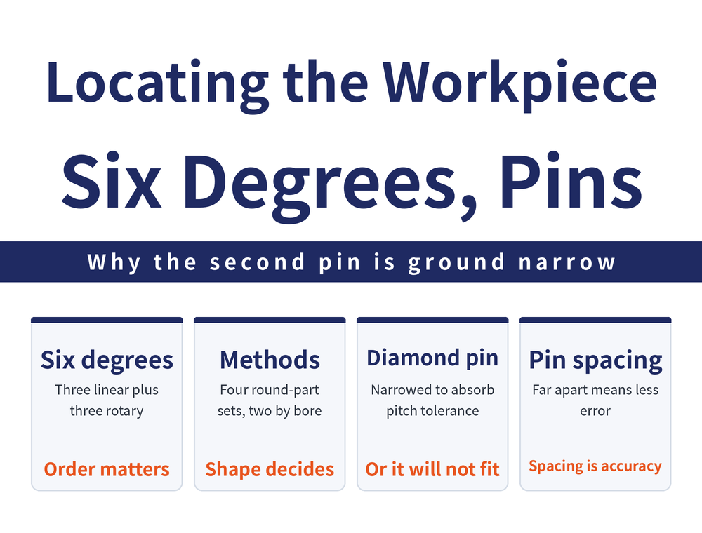
When a part goes into a fixture, the first decision is not how hard to clamp it but which single position it is allowed to sit in. Locating is about constraining the six degrees of freedom one at a time; clamping only holds the located position. This guide starts from the degrees of freedom, then covers locating methods for round and square parts, the tolerance stack-up created by two locating pins, and why one of them is narrowed into a diamond.
1. Locating, Clamping and Supporting Are Three Things
A fixture drawing carries three kinds of point with similar names and different jobs. A locating point decides where the part sits in the fixture. A clamping point is where clamping force is applied. A supporting point backs up what the clamping points do not cover, and it is movable rather than fixed.
Locate first, clamp second. Clamping force only holds a position already established; it does not find one, and no amount of it recovers a wrong locating point. Clamping too hard brings its own trouble — see Why Vise Clamping Distorts the Workpiece.
Fixture drawings also carry a colour convention:
| Marked item | Colour |
|---|---|
| Surfaces that must be machined | Red |
| Locating point | Yellow |
| Clamping point | Green |
| Supporting point | Blue |
2. Six Degrees of Freedom: What Locating Removes
Motion in three-dimensional space resolves into six degrees of freedom: linear motion along the X, Y and Z axes, plus rotation about each of those axes. Counting positive and negative directions separately gives twelve.
Locating means constraining those six one at a time. "One at a time" is the operative phrase: the constraints must be applied in sequence, not in an arbitrary order, and a square part needs the locating sequence and the locating face chosen together.
How that sequence should be ordered and which face becomes the first datum — the source gives only a conceptual heading and diagrams here, with no criteria or values, so this article does not infer any. For what a jig and a fixture are, see What Is a Jig and Fixture.
3. Four Locating Combinations for Round Parts
The source divides locating combinations into six; four belong to round parts themselves (cylinders and discs), split by whether length or diameter is greater:
| Proportion | Locating method | Key point |
|---|---|---|
| Length > diameter | Outside form and end face | Cylindrical surface plus one end face |
| Length > diameter | Centre holes | Uses the centre holes at both ends |
| Length > diameter | Held and located on the outside form | A collet or self-centring chuck locates as it grips |
| Length < diameter | Outside form plus a three-point locating plane | Grip alone cannot constrain a flat part's orientation |
Once the part is flat, the outside form gives a much shorter constraining length, grip alone no longer fixes orientation, and a three-point locating plane has to take out the rotational freedom.
4. Locating a Square Part on Its Own Hole
Square parts often need no separate datum feature: an existing hole does the work, split by the geometry of that hole.
| Hole geometry | Constraint behaviour | What the design must handle |
|---|---|---|
| Hole length > diameter | Deep enough for steadier radial and angular constraint | The hole can carry the main constraint |
| Hole diameter > depth | Shallow and wide; constraint differs from the deep case | Auxiliary constraint considered separately |
The difference is contact length along the bore wall. A deep hole stops the part tilting; in a shallow hole the same pin has little more than a ring of contact, so the angular direction must come from elsewhere.
5. Why the Second Pin Becomes a Diamond
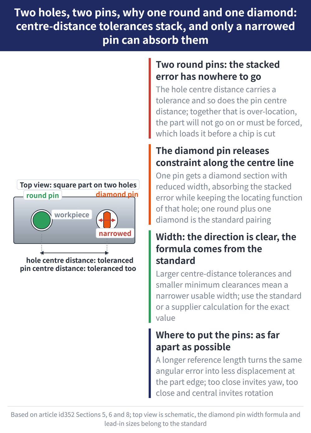
Locating a square part on two holes over two pins is the standard approach, and the problem is stack-up: the centre distance between the two holes has a tolerance, the centre distance between the two pins has one too, and they add.
With two round pins the accumulated error has nowhere to go, and the result is over-location — the part will not go on, or has to be forced on, which loads it before a chip is cut.
The diamond pin gives one pin a diamond cross-section with reduced width, releasing part of the constraint in the centre-distance direction to absorb that error while keeping the locating function the hole should provide. One round pin plus one diamond pin is the standard pairing.
6. Diamond Pin Width: Which Numbers Must Not Be Copied
The known inputs for diamond pin width are the diameter and tolerance of both locating holes, the centre distance L between them and its tolerance, the tolerance on the pin centre distance, and the minimum clearance between each hole and its pin. The width limit follows from those together.
The source does give an inequality for that limit, but the symbol sequence there is scrambled, the tolerance terms cannot be read, and the original figure was not available for verification, so the formula is not reproduced. The follow-on locating-error calculation survives only as "using the symbols from the previous page", with the formula body lost.
So this article states it plainly: the correct form of the formula is not established by the source. Use the standard itself or a supplier's calculation. The direction is clear: the larger the centre-distance tolerances and the smaller the minimum clearances, the narrower the usable width.
7. The Lead-In That Lets the Part Drop On
A lead-in at the top of a locating pin exists so the part goes into the fixture more easily. DIN 6338 lists reference dimensions, mapping pin diameter ranges to f, b and t. How each behaves as diameter grows:
| Dimension | As pin diameter increases |
|---|---|
| f | Grows step by step, by far the most of the three |
| b | Also grows, by a clearly smaller amount than f |
| t | Not at every step; several diameter bands share one value |
Only direction and order of magnitude are given here. Take actual dimensions from the DIN 6338 standard itself or a supplier catalogue — a table rebuilt from a single source has not been verified cell by cell and is not order-ready specification.
8. Where to Put the Two Locating Pins
The same two pins in different positions give very different accuracy. The source rates the relative position three ways:
| Relative position of the two pins | Result |
|---|---|
| Far enough apart | Less error; the preferred arrangement |
| Too close together | Prone to yaw error |
| Too close and near the centre | Prone to rotational error |
The logic matches measurement: the longer the reference length, the smaller the displacement at the part edge for a given angular deviation. When the hole positions are yours to choose, push them towards the ends.
Frequently Asked Questions (FAQ)
Q: What is the difference between locating and clamping?
A locating point decides where the part sits in the fixture; a clamping point only applies force to hold that position. Locate first, clamp second — if the locating points are wrong, more clamping force will not restore repeatability.
Q: Why can't both locating pins be round pins?
The centre-distance tolerance of the two holes adds to the centre-distance tolerance of the two pins. With two round pins that accumulated error has nowhere to go, which leads to over-location: the part will not go on, or must be forced on.
Q: Is there a formula for diamond pin width I can apply directly?
There is one, but this article does not reproduce it. In the source the symbol sequence is scrambled and the tolerance terms cannot be read, so the correct form of the formula is not established by the source. Use the standard or a supplier's calculation.
Q: Is there a standard for locating pin lead-in dimensions?
Yes. DIN 6338 lists reference lead-in dimensions, mapping pin diameter ranges to f, b and t. The trend is that f and b grow with pin diameter while t is shared across several bands. Take actual values from the standard or a supplier catalogue.
This article is part of Workholding and Fixtures: The Complete Guide - Locate First, Then Clamp; How Much Force and Where It Comes From; that guide shows how the whole topic fits together.









