
Face Mill Pitch Selection: Coarse, Fine and Differential
Two face mills of the same diameter can carry very different insert counts, and the difference is pitch (the spacing between adjacent cutting edges on the cutter body). Pitch sets how many edges cut at once, how much chip space each insert gets, and at what frequency the cutting force pulsates. This guide covers the trade-offs between coarse, medium and fine pitch, and why a differential pitch suppresses chatter.
1. What Pitch Is and Why It Decides the Outcome
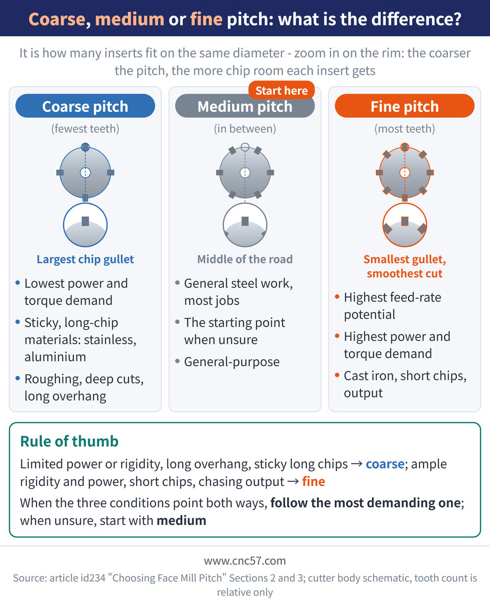
Pitch is the spacing between adjacent cutting edges on the cutter body, that is, how many inserts fit on a given diameter. Fine pitch means more teeth; coarse pitch means fewer.
The tooth count changes three things directly.
| What pitch affects | As tooth count rises | Why it matters |
|---|---|---|
| Edges cutting at the same time (number of teeth in cut, the edges actually engaged in the workpiece at any instant) | Increases | More edges means a more continuous, steadier cut, but also more power and torque demand |
| Chip space available to each insert | Decreases | Chips that cannot clear get recut and scratch the surface, and in bad cases break the edge |
| Frequency of the cutting force pulsation | Rises | Once that frequency approaches the natural frequency of the machine tool or the part, it resonates into chatter |
The three classic face milling complaints — vibration and chatter, poor chip evacuation, and not enough power — nearly always trace back to this one choice. For the wider cutter selection sequence see the Face Milling Tool Selection Guide, and for symptom-by-symptom fixes see the Face Milling Troubleshooting Guide; for where face milling sits among the milling methods, see the Milling Methods Overview.
2. Coarse, Medium and Fine: The Tool-Side Differences
None of the three is better in the abstract; each is bought for a different reason. Start with the physical differences on the tool side.
| Characteristic | Coarse pitch | Medium pitch | Fine pitch |
|---|---|---|---|
| Tooth count at a given diameter | Lowest | In between | Highest |
| Chip space per insert | Largest | In between | Smallest; gummy material packs the gullets |
| Force pulsation and smoothness | Strong pulsation, noticeable swings | In between | Weak pulsation, the smoothest cut |
| Load per edge | Can be pushed high, each edge takes a thick chip | Moderate | Lower; output is recovered through edge count |
3. Where Each Pitch Fits
Coarse pitch buys chip space and low power demand, fine pitch buys feed rate and smoothness.
| Characteristic | Coarse pitch | Medium pitch | Fine pitch |
|---|---|---|---|
| Feed rate potential | Limited by tooth count | Moderate | Highest; fastest table feed at the same feed per tooth |
| Power and torque demand | Lowest | Moderate | Highest |
| Suited materials | Gummy, long-chipping material such as stainless steel and aluminium | General steel and most everyday work | Short-chipping material such as cast iron |
| Suited machine condition | Limited power or rigidity, long overhang | The starting point when the situation is unclear | Ample rigidity and power |
| Typical positioning | Roughing, deep cuts, heavy loads | General purpose, the default starting point | Productivity and stable volume production |
The table gives general direction only; follow the catalogue or the relevant standard — not measurements taken by this site.
Keep the arithmetic in mind: table feed is feed per tooth, fz (the thickness each cutting edge removes per revolution), multiplied by tooth count and spindle speed. A fine pitch does not raise fz; it raises the overall feed rate through edge count. For the formulas see the Face Milling Formula Guide.
4. Three Conditions That Decide the Pitch
There is no rule to memorise; work through three conditions in order. When they all point the same way the choice is easy, and when they split, the most demanding one wins.
| Condition | Move toward coarse pitch | Move toward fine pitch |
|---|---|---|
| 1. Material and chip form | Gummy, long-chipping material (stainless steel, aluminium) that needs generous chip space | Short-chipping material (cast iron) whose chips break up and take little space |
| 2. Machine tool and clamping | Limited power or rigidity, long overhang, a thin part or a weak fixture | Ample machine rigidity and power, with part and fixture solidly held |
| 3. Number of teeth in cut | Wide radial engagement, where many edges already cut at once and a finer pitch would overload | Narrow radial engagement, where tooth count is what keeps edges in the cut |
The table gives general direction only; follow the catalogue or the relevant standard — not measurements taken by this site.
The rule in one line: at least one edge must always be in the cut. Intermittent contact means every edge slams back into the workpiece, and that is where vibration, edge breakage and surface marks usually start.
At narrow radial engagement the real chip comes out thinner than programmed, so the feed has to be reviewed with it — see Chip Thinning and Feed Compensation. Do not apply generic tooth counts, speeds or feeds; take them from the tool catalogue and a trial cut.
5. Why a Differential Pitch Suppresses Chatter
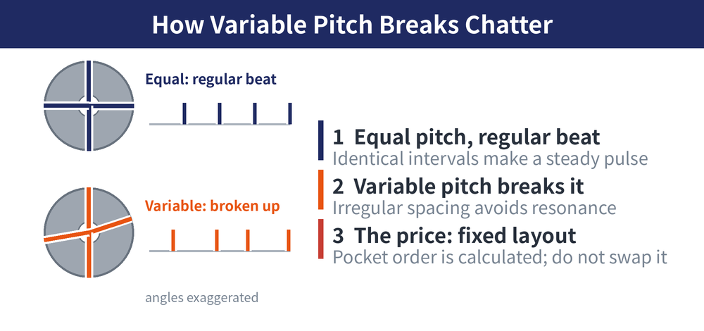
Differential pitch (also called variable pitch, where the spacing between edges is deliberately made unequal) is a design feature, not a manufacturing error. On an even-pitch cutter every edge enters at exactly the same interval, so the cutting force becomes a regular pulsation.
Make the intervals irregular and the pulsation is broken up, so it no longer lines up with the natural frequency of the machine tool or the part. This is one of the most effective chatter countermeasures available on the tool side; for the full picture of causes and remedies see Milling Chatter: Causes and Solutions.
The price is a fixed insert layout: every seat position is calculated, so inserts must be fitted and replaced in the sequence the manufacturer specifies, or the effect is lost.
6. What to Do, in Order, When Chatter Appears
There is no need to change the cutter body first; work up from the cheapest and most effective measures.
| Order | What to do first when chatter appears | Reason |
|---|---|---|
| Step 1 | Check rigidity and overhang: shorten the holder projection and confirm the part and fixture are firmly held | It costs nothing and works first; until rigidity is fixed, any new cutter will vibrate again |
| Step 2 | Adjust spindle speed, and reduce radial engagement or depth of cut if needed | Shifting the pulsation frequency moves the cut off the resonance point, and it can be tried immediately |
| Step 3 | Switch to a differential pitch cutter, or step the pitch toward coarse | It breaks up the pulsation and lowers the number of teeth in cut, which is a structural fix |
| Step 4 | Move to an anti-vibration holder where long overhang is unavoidable | When the tool side is exhausted, a damping mechanism inside the holder absorbs the vibration |
The table gives general direction only; follow the catalogue or the relevant standard — not measurements taken by this site.
For clamping and overhang practice see the Face Milling Clamping Guide, and for holder-side damping options see the Anti-Vibration Tool Holder Guide.
Last updated: 2026-08-08
7. Frequently Asked Questions (FAQ)
Q: Are pitch and tooth count the same thing?
They are two ways of saying the same thing. Pitch is the spacing between adjacent edges, so at a given diameter a coarser pitch means fewer teeth, and catalogues usually label cutters simply as coarse, medium or fine.
Q: For face milling stainless steel, coarse or fine pitch?
Generally coarse. Stainless chips are gummy and long, and without enough chip space they pack the gullets and get recut, which hits both surface quality and insert life.
Q: Is a differential pitch always better than an even pitch?
No. It solves chatter, costs more, and requires inserts to be arranged in the sequence the manufacturer specifies. With no vibration problem, an even-pitch cutter is simpler to live with.
Q: How many teeth should I choose and what feed should I set?
There are no universal values; work from the tool catalogue recommendation and confirm with a trial cut. For the conversion method, see the Face Milling Formula Guide.
For the full reading guides on this topic, see Insert Selection: A Complete Reading Guide and Vibration and Chatter: A Complete Reading Guide.









