
Boring on the Lathe: Setting Tool Angles and Why the Bore Grows or Shrinks
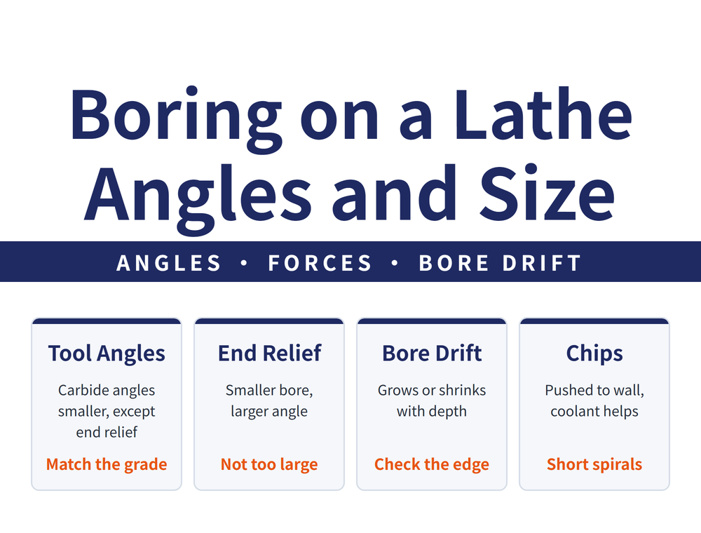
Boring on a lathe means the part turns while the bar reaches into the hole: the bar deflects easily, you cannot see the cut and the size is hard to measure, so it is harder than OD turning. On ground boring tools, carbide angles are usually smaller than or equal to high speed steel, and smaller bores need a larger end relief angle. If the bore grows or shrinks as it goes deeper, check the cutting edge angle first: an edge close to square to the feed direction bores straight.
1. When to bore on a lathe, and why it is harder than OD turning
When the hole size is unusual or too large for a suitable drill, the hole is bored on the lathe with a boring tool. There are four reasons to bore: to improve the rough wall left by drilling, to correct a bell-mouthed or barrel-shaped hole, to open the hole beyond what a drill can reach, and to bring the diameter to an exact size.
It is harder than OD turning for three reasons: the bar deflects easily inside the hole, you cannot see the cutting point, and the size is harder to measure. This article covers lathe boring, where the part turns and the bar does not; for bar codes see Boring Bar Guide: ISO Codes, Material & Selection, and for boring with rotating tools on a machining centre see Boring Basics: Four Boring Methods and the Rigidity-First Rule.
2. Six kinds of holes, two kinds of tools
| Hole | What it looks like |
|---|---|
| Through hole | One diameter, right through the part |
| Blind hole | Like a through hole, but not through |
| Stepped hole | Two concentric bores of different diameters |
| Eccentric hole | Two bores, not concentric, of different diameters |
| Taper hole | Seen from the cutting side, largest at the front, smallest at the back |
| Threaded hole | A thread of fixed pitch cut in the wall |
Boring tools mainly cut through, stepped and taper holes. Internal grooving tools cut the thread relief groove, which gives the internal threading tool a place to stop and retract; without it the tool hits the bottom or leaves an incomplete thread. Retaining ring grooves and O-ring grooves use them too.
3. Ground boring tools: setting the six angles
Brazed or solid boring tools are ground by hand. The table gives common starting ranges; adjust for the material and the job.
| Angle | High speed steel | Carbide | What it does |
|---|---|---|---|
| Side cutting edge angle | 3°~8° | 3°~5° | Less rubbing, a keener edge |
| Side relief angle | 5°~8° | 3°~6° | Less rubbing between the part side and the tool |
| End relief angle | 8°~10° | 8°~10° | Lets the edge cut in; poorly ground, a deep cut chips the tip |
| End cutting edge angle | 8°~12° | 5°~10° | Edge strength; keeps the tool heel off the wall |
| Back rake | 8°~15° | 3°~5° | Edge strength and chip direction |
| Side rake | 8°~15° | 3°~5° | Clears chips off the face, less heat |
Two patterns: carbide is more brittle, so apart from the end relief angle, which is the same for both, the other five carbide angles are smaller or equal, never larger. Because a boring tool is surrounded by the wall, its side cutting edge angle is also much smaller than on an OD tool.
4. Set the end relief angle by bore size
The smaller the bore, the more easily the underside of the bar rubs the wall and interferes with the cut, so the end relief angle must grow as the bore shrinks. Too large, though, and the edge becomes weak and dulls quickly. The angle is a compromise between these two opposite pressures.
5. The bore grows or shrinks with depth: check the edge angle first
On a rough boring tool, the cutting edge angle decides where the cutting resistance pushes the tool. Ground off, the resistance either pushes the tool into the wall, so the bore grows with depth, or away from it, so the bore shrinks. With the edge close to square to the feed direction, the resistance runs almost along the bar, the tool does not drift in or out, and the bore stays parallel.
So when the size changes with depth, check the edge angle before blaming the machine. Indexable bars follow the same logic: the closer the entering angle is to 90°, the smaller the radial force and the less the bar deflects. If the tool is fine and the size still drifts, look at heat and tool wear; see Turning Troubleshooting Guide | Tool Wear, Accuracy and Surface Issues.
6. Three forces on the bar, and choosing the nose radius
Cutting force in boring has three components: the tangential force pushes the tool down and off the centre line, reducing the secondary clearance; the radial force changes the depth of cut and chip thickness, taking the size out of tolerance and inviting vibration; the feed force acts along the feed. A bar as thick and as short as possible is how you hold the resulting deflection down.
Choose a nose radius slightly smaller than the depth of cut. Both too large and too small a chip area cause vibration: too large from high cutting force, too small from too much friction between tool and part, so a very light cut can chatter too. For vibration troubleshooting in full, see Boring Troubleshooting: Vibration, Chips, Feed Marks and Power.
7. Chips head for the wall: evacuation and clamping
Centrifugal force from the turning part throws chips against the wall, where they are hard to clear and can damage the bore; internal coolant helps. The ideal chip is a short spiral: long chips can jam in the hole, and hard, short broken chips take more power and speed up wear.
Clamping length, how far the bar can reach, the minimum entering angle and the preferred insert clearance are covered in section 4 of Boring Bar Guide: ISO Codes, Material & Selection; part-side toolpaths and small-bore geometry limits are in Toolpath Planning for Overhung Workpieces and Small Bores: Stock Removal Passes, Zero-Point Drift and Boring Bar Geometry Limits.
8. Frequently Asked Questions (FAQ)
Q: The bore gets smaller as it goes deeper. Is it the tool?
Check the tool first. When the edge angle of a rough boring tool is ground off, the cutting resistance pushes the tool away from or into the wall, so the size shrinks or grows with depth; with the edge close to square to the feed direction the bore stays straight. If the tool is fine, look at heat and wear.
Q: Should carbide boring tool angles be larger or smaller than high speed steel?
Smaller or equal. Of the six angles only the end relief angle is the same for both, at 8°~10°; the other five are never larger on carbide, because carbide is more brittle and the edge needs more support.
Q: Why does a smaller bore need a larger end relief angle?
In a smaller bore the underside of the bar rubs the wall more easily and interferes with the cut, so the angle is increased; too large, and the edge becomes weak and dulls fast, so it is a compromise.
Q: Why is boring harder than OD turning?
The bar deflects inside the hole, you cannot see the cut and the size is harder to measure; keep the bar as thick and short as possible and pay close attention to chip evacuation.
Last updated: 2026-10-22
For the full reading guide on this topic, see Hole Accuracy: A Complete Reading Guide.









