
Boring Basics: Four Boring Methods and the Rigidity-First Rule
Boring takes an existing hole and brings it to the target size, position and surface finish, usually on a machining centre or horizontal boring machine with a rotating tool feeding axially. This guide covers the four boring methods and the thread that runs through all of it: tool rigidity and overhang.
1. What boring actually does
The difference between boring and drilling is the starting point: drilling opens a new hole in solid stock; boring takes over an existing hole and enlarges, corrects or tightens it into tolerance. Its home ground is machining centres and horizontal boring machines, on prismatic parts such as housing frames.
The boring power formula is not the turning one
The net power formula for boring carries one extra correction term compared with turning and drilling: Pc = (vc × ap × fn × kc ÷ 60000) × (1 − ap ÷ DC), where ap is the depth of cut and DC the bore diameter. The larger the depth of cut relative to the bore diameter, the more that correction matters. For cutting speed, spindle speed and feed, feed the numbers through the Machining Formulas Cheat Sheet: Turning, Milling, Drilling, Boring.
2. The four boring methods: how roughing hands over to finishing
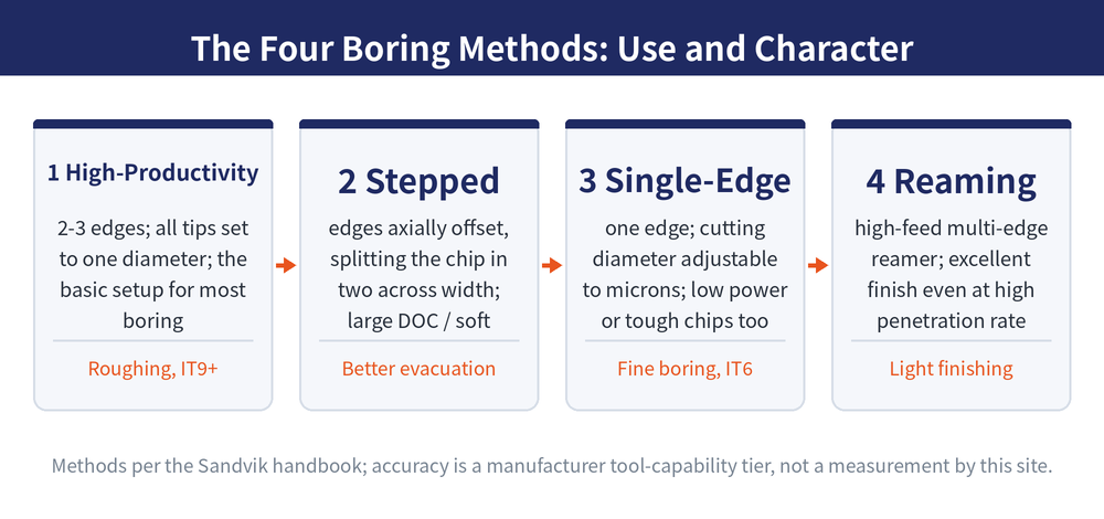
Split by edge count and task, these four are what you meet most; they form a relay from rough to fine.
| Method | Edges | When to use | Key feature |
|---|---|---|---|
| High-productivity boring | 2–3 edges | Roughing where metal removal rate comes first (hole tolerance about IT9 or wider) | All edges set to the same diameter and height; feed = feed per edge × number of edges; the basic setup for most boring |
| Stepped boring | Multi-edge (axially offset) | Large radial depth of cut, or soft (long-chipping) materials | Edges set to different heights and diameters, splitting one full-width chip into two that clear more easily |
| Single-edge boring | 1 edge | Demanding chip control (long chips), or limited machine power; fine boring to the tightest tolerance | One slide only; cutting diameter adjustable to micrometre resolution, the first choice for fine boring |
| Reaming | Multi-edge | Light finishing, high volume | High-feed multi-edge reamers that still give an excellent finish at high penetration rates |
3. The first rule of tool choice: rigidity and torque transmission
On tool choice, the manufacturer handbook says one thing: rigidity and reliable torque transmission are the most important factors. Applied to overhang, that means the shortest and largest adapter you can fit, a tapered adapter where possible, and a rigid flange-to-spindle face clamp on long overhang; once overhang exceeds 4× the interface diameter, switch to a dampened adapter. For the five principles point by point, as a pre-job checklist, see Fine Boring and Tool Overhang: Single-Edge Tools and Five Principles.
The "switch to a dampened tool once overhang exceeds 4× the interface diameter" figure is a general threshold from the manufacturer (Sandvik) handbook, not a measurement by this site; follow the manufacturer's specification. For selecting the boring bar itself, see the boring bar model guide: ISO boring bar selection and specifications.
4. Rough boring versus fine boring: how the tools divide
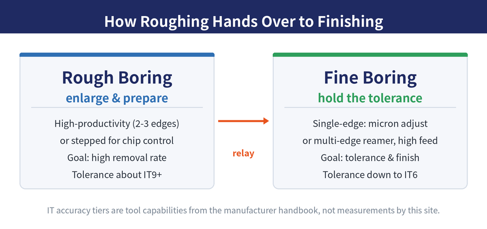
Rough boring enlarges the hole and prepares it for finishing; fine boring brings it to the specified tolerance and surface finish. On the roughing side, the common trade-off is two edges or three: three edges on medium-to-large power for best productivity (and they can be reset to single-edge or stepped); two edges on low-to-medium power, unstable operations or large diameters (a lighter assembly with less impact, steadier on large diameters). For the full comparison and how to pair rake and entering angle, see Rough Boring Tool Selection: Edges, Rake and Entering Angle.
On the finishing side, the single-edge fine boring tool is the first choice, with adjustment resolution in the micrometre range. The dampening threshold matches roughing: overhang beyond 4× the interface diameter.
5. Bringing the tolerance in: single-edge fine boring and reverse compensation
Multi-edge rough boring, single-edge fine boring and finishing reamers cover roughly IT6 to IT9. The key is single-edge fine boring's tool deflection: the edge deflects radially under load and leaves the hole undersize, so you use reverse compensation — estimate the deflection in advance and set the tool a little larger; for a target hole of Ø25mm H7, set the actual cutting diameter to Ø25.021mm, 0.021mm above nominal, so the hole after deflection lands right in the tolerance band. For why depth of cut and overhang amplify the deflection, see Section 3 of Fine Boring and Tool Overhang: Single-Edge Tools and Five Principles.
Make the final adjustment with the tool still in the spindle after measuring the diameter, then take one trial cut to confirm. For how tolerance passes from tool to hole, read how to improve hole accuracy: IT tolerances and the drill / ream / bore route.
6. Coolant and chips: chip evacuation is the make-or-break of blind holes
Boring is often into blind or deep holes, where chip evacuation is hard. The manufacturer recommends internal coolant first, with an ideal chip shape that is comma-shaped or spiral; the maximum initial cutting speeds by case are about 200 m/min for rough boring, about 240 m/min for fine boring with a fine boring adapter, and about 90–120 m/min for fine boring with a fine boring bar. For what goes wrong when speed is too high or too low, see Boring Chip Control and Coolant: Internal Coolant, Chip Shape and Speed Limits.
These are maximum initial cutting speeds from the manufacturer (Sandvik) handbook — factory reference values, not universal recommendations and not measurements by this site; follow the manufacturer's specification, and convert them to spindle speed with the Machining Formulas Cheat Sheet: Turning, Milling, Drilling, Boring.
The fine boring adapter and bar differ by more than double in recommended speed, because their rigidity differs. Also note: when fitting a dampened tool, never clamp on the bar body itself, or you crush the damping mechanism and lose the effect.
7. Troubleshooting common boring problems
When boring goes wrong, nine times out of ten it involves vibration, chips or power, so sort it first: for tool vibration, lower feed and speed, switch to stepped boring, use a smaller nose radius, keep overhang short and switch to a dampened tool if needed; for chips too short and hard, raise cutting speed moderately, lower feed and change to a more open chip breaker, while chips too long take the opposite — raise feed, lower speed, change to a more closed chip breaker; for limited machine power, lower the cutting parameters, switch to stepped boring, reduce the number of engaged inserts and reduce depth of cut. For the causes and full countermeasures of each symptom, see Boring Troubleshooting: Vibration, Chips, Feed Marks and Power.
The easiest to get backwards is depth of cut: in roughing, vibration calls for less depth, but in finishing, vibration calls for more depth. For probe types and reading error see the inside-diameter measurement guide, and for the surface roughness each process reaches see the process-versus-surface-roughness chart.
8. How to read the boring series: tool choice and the rough-to-fine split
The site's boring technical information runs to 14 articles, and this one is the entry point: sort out the four methods and the rigidity rule here, then read on by the problem in hand.
Edges, rake and entering angle for rough boring are in Rough Boring Tool Selection: Edges, Rake and Entering Angle; fine boring tools, holder parameters and the five overhang principles in Fine Boring and Tool Overhang: Single-Edge Tools and Five Principles; rotating boring bars and heads on a machining centre (rigidity, micro-adjust, coolant) in Boring Bar and Head Selection: Rigidity, Micro-Adjust and Coolant Delivery; lathe boring bar codes in Boring Bar Guide: ISO Codes, Material & Selection; tool angles and bore size drift when boring on a lathe in Boring on the Lathe: Setting Tool Angles and Why the Bore Grows or Shrinks; and boring canned cycles on a machining centre, retracting without marking the wall, in Choosing a Boring Cycle: How G76 and G85-G89 Differ.
9. How to read the boring series: troubleshooting and regrinding
When something goes wrong: vibration, chips, feed marks and power are in Boring Troubleshooting: Vibration, Chips, Feed Marks and Power; chip evacuation, coolant and cutting speed limits in Boring Chip Control and Coolant: Internal Coolant, Chip Shape and Speed Limits; and ultrasonic vibration dry boring in Ultrasonic Vibration Dry Boring: Pulse Cutting and the Critical Speed.
Regrinding and repair: the reamer rake face, flank and finish are in Regrinding a Reamer: Rake Face, Flank and How Fine the Ground Surface Must Be; carbide and special reamers in Regrinding Carbide and Special Reamers: Tilt Angle, Transition Edge Position and Three Structures; repairing an oversize or worn reamer in Oversize or Worn Reamers: Lapping, Peening and Scrape-Expansion Repair; and regrinding a floating boring tool in Regrinding a Floating Boring Tool: Three Angle Blocks and the Precision Route.
Last updated: 2026-10-22
10. Frequently Asked Questions (FAQ)
Q: How does boring differ from drilling, and when should I add a boring pass?
The difference is the starting point: drilling opens a new hole in solid stock, while boring takes over an existing hole to tighten it into tolerance. Add a boring pass after drilling when the drawing calls for a tolerance tighter than the drill's own, a straighter hole position, or better roundness and finish.
Q: How do I quickly choose among high-productivity, stepped, single-edge and reaming?
General roughing takes high-productivity boring (2 to 3 edges, IT9 and wider); a large radial depth or soft long-chipping material uses stepped, short power or demanding chip control uses single-edge, and the final precise pass uses high-feed multi-edge reaming. Single-edge boring is also the first choice for fine boring to the tightest tolerance.
Q: Why is boring especially prone to vibration and long overhang?
Because a boring bar is a cantilever, the longer the overhang the more it deflects and vibrates. Countermeasures: use the strongest interface for the shortest overhang, the largest possible adapter diameter, and a dampened tool with tapered adapter once overhang exceeds about 4× the interface diameter — and never clamp a dampened tool on the bar body. See Boring Bar and Head Selection: Rigidity, Micro-Adjust and Coolant Delivery for details.
Q: Why deliberately set the fine boring tool a little oversize?
To compensate for radial deflection, which leaves the hole undersize, you use reverse compensation — for a target of Ø25mm H7, set the tool cutting diameter to Ø25.021mm. Make the final adjustment with the tool still in the spindle after measuring the diameter, and take one trial cut to confirm.
For the full reading guides on this topic, see Vibration and Chatter: A Complete Reading Guide and Hole Accuracy: A Complete Reading Guide.









