
How to Prevent Tool Dig-In on a Lathe: Leadscrew Backlash, Quadrant Changes and Lead Angle Choice
Halfway through an arc the nose suddenly sinks into the finished surface, leaving a gouge or even breaking the edge — that is tool dig-in. This guide explains what happens at the instant an arc path crosses a quadrant boundary, and how leadscrew drive backlash lets the radial force component push the nose into the part. It then compares the 100°–105° and 10°–15° lead angle approaches, explains why the cross slide starts to crawl, and lists five causes of dig-in when turning steel with what to check for each. For the causes, go straight to the table in section 5.
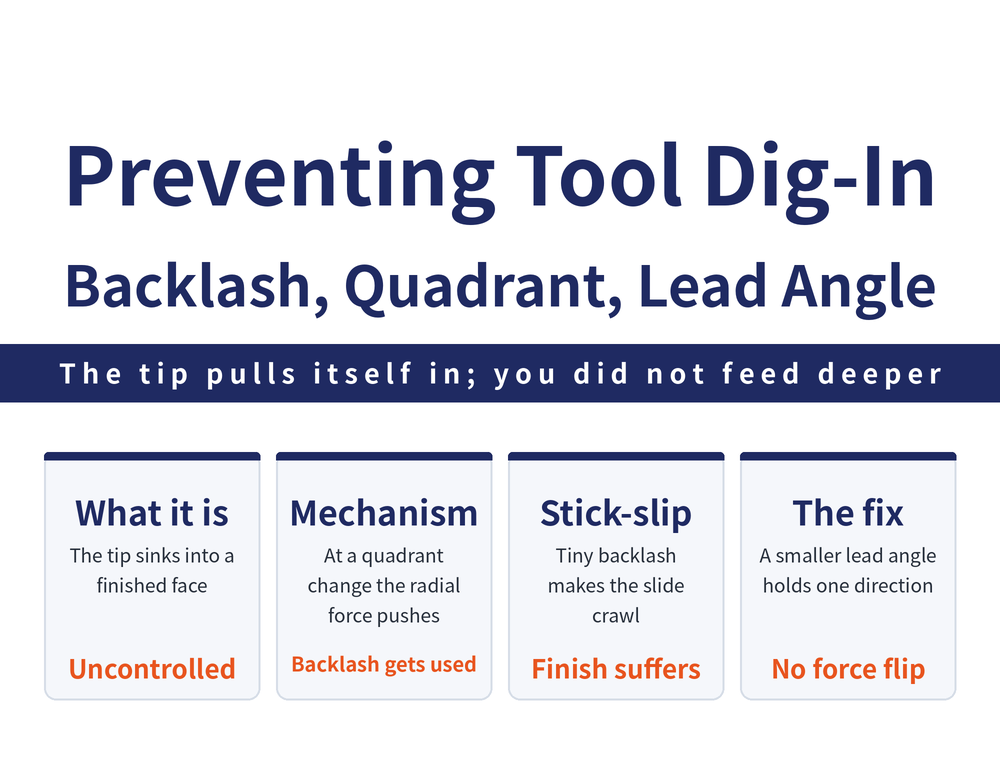
One naming note first: Chinese-language machining texts write this failure as zha dao, and Taiwanese shop floors also call it qian dao — both mean the same thing, the tool nose sinking into the finished surface out of control. This guide uses dig-in throughout. For how a turning path is planned as a whole, see How to Plan a Turning Feed Path.
1. Dig-In Is Not Simply a Wrong Feed Direction
On a CNC lathe the Z axis is normally fed in the negative direction. That is the convention, but it is not always the right choice, and it can go as far as ruining the workpiece and damaging the tool.
The clearest case is a pointed turning tool cutting a large internal arc. Same arc, same lathe: change only the infeed approach and the outcome changes. One version digs in and crawls, the other does neither. The difference is not spindle speed and not feed rate, but whether the cutting force direction holds the drive backlash closed.
2. The Mechanism: at the Quadrant Change, the Backlash Opens Up
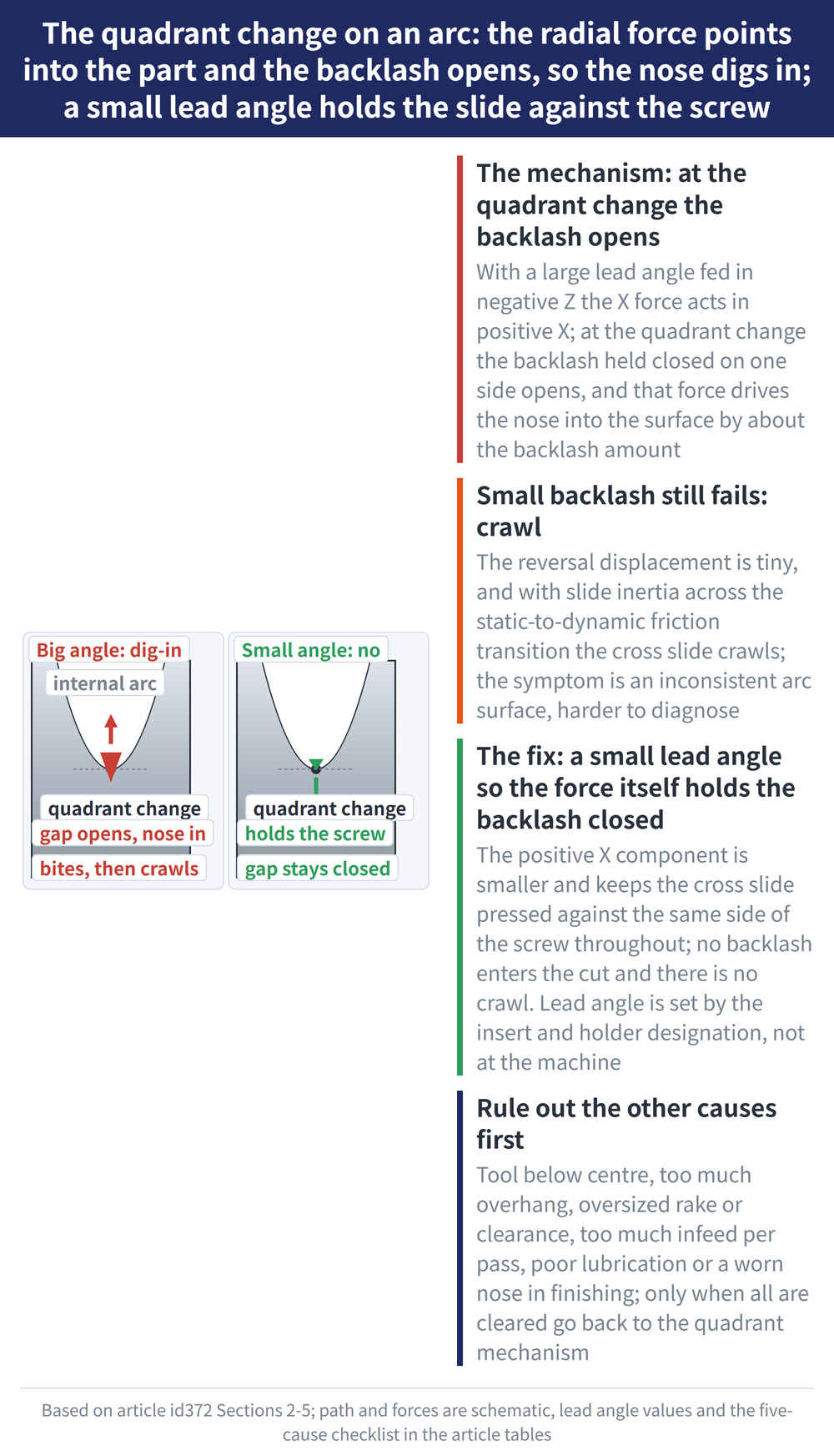
Start with the version that fails. With a lead angle of 100°–105° fed in the negative Z direction, the X component of the cutting force, Px, acts in the positive X direction.
The feed motion is subject to mechanical backlash in the leadscrew drive. When the nose reaches the quadrant change point of the arc — where motion switches from negative Z, negative X to negative Z, positive X — the backlash that was held closed on one side opens up, and Px can drive the nose into the surface of the part. That is dig-in.
The depth of the bite theoretically equals the mechanical drive backlash e. That is a qualitative cause-and-effect relation, not a formula to substitute into. Actual reversal backlash differs from machine to machine, so use your own measurement or the machine builder's data.
3. Small Backlash Still Fails: Crawl
A common assumption is that a machine with very little backlash cannot dig in. In practice small backlash only changes the form the problem takes.
When the backlash is small, the change in cross slide displacement as the nose reverses in X is also small. Combined with slide inertia during the transition between static and dynamic friction, this still produces severe crawl of the cross slide, which greatly reduces surface quality.
So this family of problems shows up in two ways: one visible gouge, or a whole arc whose surface is inconsistent. The second is harder to diagnose, because the tool and the parameters all look normal.
4. The Fix: Change the Lead Angle to 10°–15°
The sound approach is to change the tool geometry so the cutting force itself holds the backlash closed. With a lead angle of 10°–15°, the force component in the positive X direction is smaller, and that component keeps the cross slide pressed firmly against the leadscrew in the positive X direction at all times.
The backlash stays closed on the same side from start to finish, so the drive backlash of the screw pair never enters the cut and there is no crawl. The two approaches compare as follows:
| Item | Lead angle 100°–105° (unsound) | Lead angle 10°–15° (sound) |
|---|---|---|
| Force component in +X | Larger | Smaller |
| Relation to the leadscrew | Backlash opens at the quadrant change | Held against the same side throughout |
| At the quadrant change | Nose may bite in, roughly by the backlash e | Unaffected by drive backlash |
| Crawl | Severe cross slide crawl | No crawl |
| Verdict | Not advised on large internal arcs | The more sound infeed choice |
Lead angle is fixed the moment the insert and holder designation is chosen; it is not a parameter that can be adjusted at the machine. For how designations map to lead angle, see How to Read ISO Turning Insert Designations.
5. Five Causes of Dig-In When Turning Steel
The sections above cover dig-in caused by path and geometry. When turning ductile material such as steel, several other causes are common on the shop floor, listed here for comparison:
| Cause | Why it digs in | Check first |
|---|---|---|
| Tool clamped below the part axis | Working angles differ from the design values | Nose centre height |
| Tool overhanging too far | Large deflection under load | Overhang length |
| Rake or clearance angle too large | Radial force pulls the tool into the cut surface | Insert geometry, reground angles |
| Large infeed in a single pass | Large contact area, chip evacuation is difficult | Number of passes, chip form |
| Poor lubrication and heavy nose wear in finishing | Cutting force rises and becomes unsteady | Coolant supply, nose wear |
Of the five, the first four are ruled out by checking the tool and the clamping, the fifth by checking coolant and tool condition. Only when all of them are ruled out is it worth going back to the quadrant change mechanism in section 2.
6. Dig-In in Thread Turning: Start With the Infeed Method
Thread turning is where dig-in concentrates, because one thread is cut over many passes and the way the cutting edges engage on each pass changes both the cutting force and how easily chips clear.
Comparing the infeed methods themselves is outside the scope of this guide. For how to choose between radial infeed, flank infeed and alternating flank infeed, see Thread Infeed Methods Explained, which tabulates the advantages and drawbacks of all three.
Only one selection rule is kept here: the infeed method has to match spindle speed. At higher lathe speeds the radial (straight) infeed is preferred; at lower speeds a flank infeed cutting on one edge can be used instead to lower the dig-in risk.
7. Scope and Sources
The quadrant change mechanism described here is derived from the case of a pointed tool cutting a large internal arc. It describes a qualitative cause-and-effect relation; measure the actual backlash on your own machine.
To judge the magnitude on a real machine, use the reversal backlash you measure yourself. The trigonometry of lead angle and cutting force resolution is not covered here; for the everyday turning calculations, see Turning Machining Formulas.
For the full reading guide on this topic, see Turning Toolpaths: The Complete Guide.
8. Frequently Asked Questions (FAQ)
Q: Are zha dao and qian dao the same thing?
They are two names for the same failure, both rendered as dig-in here: the tool nose sinking into the finished surface out of control, leaving a gouge and surface defects at best, and ruining the workpiece or damaging the tool at worst. Note that dig-in when ramping a milling cutter and dig-in at a turning quadrant change are different physical mechanisms and should not be conflated.
Q: Why are arcs especially prone to dig-in?
Because an arc path always crosses a quadrant change point. At the instant the X motion of the nose reverses from negative to positive, the mechanical backlash in the leadscrew drive opens up, and if the radial force component happens to act towards the part the nose is pushed in, theoretically by the amount of the drive backlash e. Straight turning has no such reversal point, so it does not fail this way.
Q: Does a 10°–15° lead angle guarantee no dig-in?
It addresses one cause, the leadscrew drive backlash. A small lead angle keeps the positive X force component small and keeps the cross slide pressed against the same side of the leadscrew, so neither backlash nor crawl enters the cut. Wrong centre height, excessive overhang, oversized rake or clearance angles and a worn nose do not go away with it, and have to be checked separately.
Q: The surface is inconsistent but there is no visible gouge. Is that dig-in?
It may be the same mechanism in another form. When drive backlash is small, the change in displacement as the nose reverses is small too, and with slide inertia during the static to dynamic friction transition the cross slide crawls badly. The result is a whole stretch of degraded surface rather than a single bite mark. Check whether the problem clusters near the quadrant change points of the arc.
Published: 2026-08-28 | Last updated: 2026-08-28









