
Turning Toolpaths: The Complete Guide — Where the Tool Goes, How to Cut Air Time, and How to Prevent Dig-In and Distortion
The same insert at the same speed and feed gives different cycle times, different finishes and different scrap rates depending on the path the tool takes. This guide ties the path layer of turning together: plan a feed path, cut the air time, choose a roughing strategy, keep the finishing pass continuous, and handle dig-in, thin walls, overhang and deep holes. Every section points to an article you can read next.
1. First, what this line is not about
Turning content on this site sits in three layers. They answer different questions, and looking in the wrong layer is why an answer seems missing:
| The layer asks | Typical question | Where to look |
|---|---|---|
| Which tool | Insert code, holder, grade, angles | The turning tool selection process line |
| Which conditions | Speed, feed and depth of cut | Turning calculation formulas |
| Where the tool goes (this guide) | Entry point, path, retract, sequence | Read on |
The three interact, but none of them substitutes for another. The right insert at the right speed will still crash, and will still distort a thin wall, if the path and the sequence are wrong. That is why the path layer is written as its own line here rather than folded into the selection or calculation articles.
2. What a feed path is made of
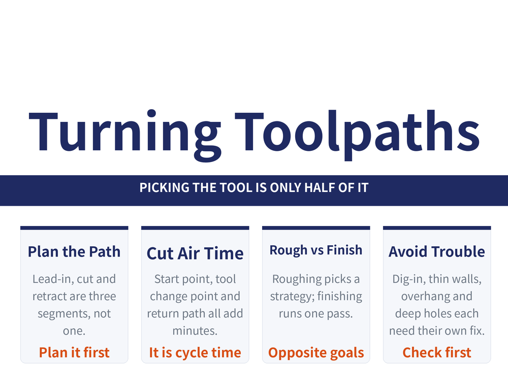
Start with the anatomy, so the later sections share a vocabulary. Lead-in, cut and retract are three segments, not one. Only the middle segment removes material; the two on either side decide safety and whether the surface carries a witness mark.
| Article | When to read it |
|---|---|
| How to plan a turning feed path | The entry point for the whole line. Covers the definition, the four planning principles and the three lead-in and retract methods |
| Lead-in and overtravel length chart | When you need the numbers: how many mm for the delta 1 and delta 2 allowances, and the accel and decel zone for thread turning |
The split between the two is simple: the first explains why the path is arranged that way, the second is a lookup table. Under time pressure go straight to the table, but for a part you have never run before, read the four principles first.
3. Time spent not cutting is still time
Cycle time is not just the cutting passes. Where the start point sits, where the tool change point sits, and whether the tool returns to zero every time makes little difference on a one-off, and a large difference once the quantity climbs.
| Article | When to read it |
|---|---|
| How to cut rapid travel in turning | When a program runs longer than expected, or when the same part is going to be made in quantity. Three techniques: start point, tool change point and return path |
Note that how much air time you can actually save depends on the machine and the workholding, and the spread between machines is wide. That article gives the direction and the way to judge it, not figures to copy.
4. Roughing: pick a strategy, and set the finishing allowance
Roughing has one goal: remove the excess in the least time. Surface quality is not this pass's responsibility. The wrong strategy multiplies the time for the same volume of material, and the wrong allowance leaves the finishing pass with a problem it cannot fix.
| Article | When to read it |
|---|---|
| How to choose a rough turning path | Facing a new profile and unsure whether to use the rectangular, triangular, closed compound or concave arc strategy. All five compared |
| Depth of cut and finishing allowance | When deciding between one pass and two, and how much material to leave for finishing |
Note that the comparison table in the roughing article has cells left blank on purpose. No reliable figure exists for those entries and this site does not fill them in by inference. Read the populated columns; a blank means no reliable figure is available, not that there is no difference.
5. Finishing: why the pass should be continuous
Finishing runs on almost the opposite principle. What it needs is consistent size and surface, and consistency's worst enemy is stopping part way. Every stop adds a witness mark, and the elastic recovery of the tool at the stop leaves a size step as well.
| Article | When to read it |
|---|---|
| Why a finishing pass runs continuous | When the profile shows witness marks, or when sizes on different segments of one profile disagree. Also covers two uses for a parting blade |
Note that a poor finish is not always a path problem. Every process has a capability limit of its own, and past that limit no amount of path planning will reach the number. That belongs to the surface roughness line, not to this one.
6. The four ways it goes wrong
The sections above are about going faster and cleaner. This one is about not wrecking the part. The four have different causes and the countermeasures are not interchangeable.
| Article | When to read it |
|---|---|
| Preventing tool dig-in | When the tool suddenly bites in while turning an arc or crossing a quadrant. Linked to leadscrew backlash and lead angle choice |
| Sequencing a thin wall part | When measurements wander, or the size changes again after the part comes out of the chuck. Three passes and four distortion countermeasures |
| Overhung parts and small bores | When the part sticks out too far, or the bore is too small for a normal boring bar |
| Deep hole pecking rhythm on a lathe | When drilling a deep hole on the lathe and deciding how far to go between retracts |
The worked figures in the overhang and deep hole articles each carry an explicit precondition (part diameter, length to diameter ratio, hole depth ratio); they must not be extrapolated to other sizes, so read the precondition with the number. If the vibration is not path related - forced vibration or self-excited chatter, for instance - that belongs to the vibration and chatter line and is not covered here.
7. Threads, parting and grooving follow their own rules
These three do not follow the logic of general outside diameter and face turning, so the principles above do not transfer directly.
| Article | When to read it |
|---|---|
| CNC thread cutting depth | When setting how many passes a thread takes and how deep each one cuts |
| Thread infeed methods | When choosing between radial, flank and alternating flank infeed |
| Parting off | When things go wrong near the centre. The difficulty of parting is concentrated in the last short segment |
| Grooving operations | For general grooves, circlip grooves and face grooves, which run three different ways |
This section covers only the path related articles. The full thread system, covering profiles, tolerance classes and lookup tables, is a separate line and outside the scope of this guide.
8. Frequently asked questions
Q: There are a lot of articles here. Which one comes first?
Start with the feed path planning article in section 2. It is the entry point and explains the three segments of a path and the four planning principles. After that go by symptom: section 3 if the cycle feels slow, section 4 to choose a roughing strategy, section 5 if the finish is poor, and section 6 if something has already gone wrong.
Q: The tool and the cutting data are both right and it still comes out badly. Can the path be the cause?
It can, and this is the layer most often overlooked. Tool and conditions decide how much one pass can take; the path decides where that pass comes from, where it goes and what follows it. Witness marks, a thin wall that distorts once released from the chuck, and a tool that suddenly digs in on an arc all have little to do with tool choice or cutting data. They are path and sequence problems.
Q: Why are the roughing and finishing principles almost opposite?
Because the goals differ. Roughing wants the most material removed per minute, so the path may be split and may double back as long as the total time is short. Finishing wants consistent size and surface, and its worst enemy is stopping and re-entering, so it runs one continuous pass. Rough thinking applied to finishing leaves witness marks; finish thinking applied to roughing multiplies the cycle time.
Q: Can the figures in these articles be used directly?
It depends on how each one is labelled. The lead-in and overtravel article is a lookup table with its conditions stated beside it. The worked values in the overhang, small bore and deep hole articles each carry an explicit precondition such as part diameter, length to diameter ratio or hole depth ratio, and they must not be extrapolated. The roughing comparison table has cells deliberately left blank where no reliable figure exists. The rule is to carry the precondition with the number, and not to move a figure that has none.
Published: 2026-08-30|Last updated: 2026-08-30









