
How to Plan a Turning Toolpath: Definition, Four Principles and Three Retract Methods
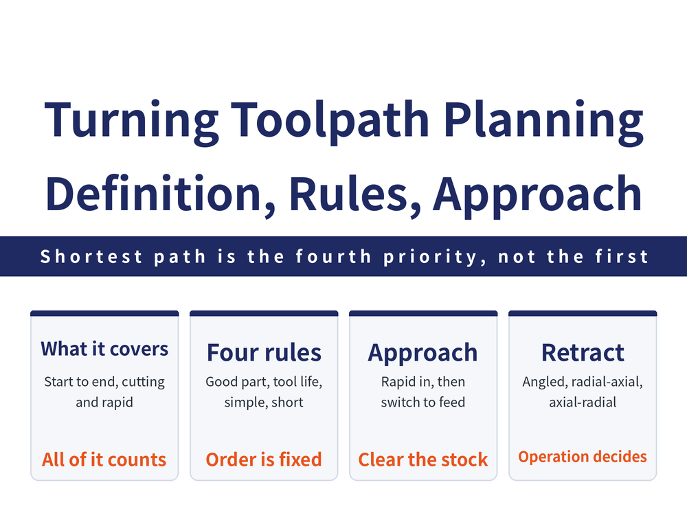
A turning toolpath is the whole route the tool travels from the moment the program starts moving it to the moment the program stops it — cutting passes and the non-cutting approach and exit moves alike. This guide covers the definition of the toolpath, the four principles to weigh when planning one, how to set the rapid approach and the entry clearance before the cut, how to exit and retract after it, and which of the three retract methods — angular, radial-axial, axial-radial — suits which operation. For the short answer, go straight to the retract table in section 5.
Many people read the toolpath as “where the tool cuts”, but it is counted from the first line of the program, and the travel before the tool ever touches the part costs cycle time too. For the order in which operations themselves are sequenced, see How to Plan the Machining Sequence. This article stays inside one operation and looks at how the tool moves.
1. What a Feed Path Is: From Program Start to Program Stop
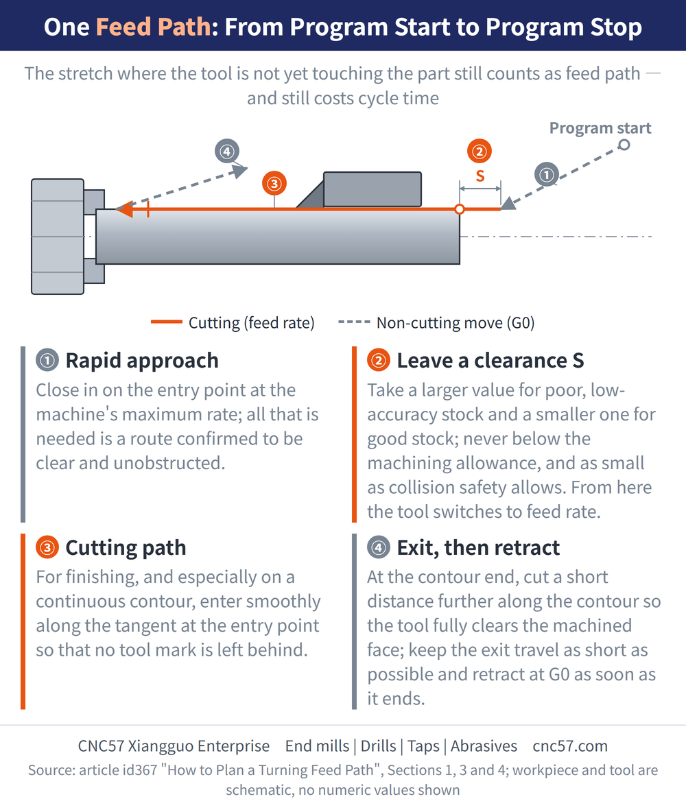
A feed path is the route the tool travels from the moment the program starts moving it until the program stops it, covering both the cutting passes and the non-cutting moves such as approach and exit.
It is the trajectory of the tool through the whole operation. It carries not only the content of each step but also their order, which is why it is a primary basis for programming: how the steps are divided and arranged is generally settled by the feed path.
The planning effort belongs mainly to roughing and to the non-cutting moves. Finishing passes essentially follow the part contour, so there is little room to move; what opens up a gap in cycle time is how roughing is divided into passes and how far the tool travels while not cutting.
2. The Four Principles of Feed Path Planning
Four things have to be weighed at the same time when a feed path is set:
| Principle | What it protects |
|---|---|
| 1. A sound part | The route must favour producing a part that passes |
| 2. Tool life | The route must favour the life of the tool |
| 3. Simple calculation | Keep the data easy to work out, reduce programming effort |
| 4. Shortest route | Fewer blocks, less air cutting time, higher efficiency |
These four sometimes contradict one another. The shortest route is not always the kindest to the tool, and the easiest route to calculate is not always the shortest. When they clash, separate the primary from the secondary, secure what matters most and accommodate the rest, rather than forcing all four to be optimal at once.
3. Before the Cut: Rapid Approach and Entry Clearance
Before cutting begins the tool sits well clear of the workpiece. That leg is normally driven at the machine tool's maximum traverse rate (G0) toward the entry point, and all it has to satisfy is that the route is clear of obstructions.
A clearance S is left between the end of the rapid move and the entry point, sized according to the condition of the stock at that entry point:
| Condition | How to set clearance S |
|---|---|
| Stock of poorer quality, low accuracy | Take a larger value |
| Stock of better quality, high accuracy | Take a smaller value |
| Lower bound in both cases | It must be greater than the machining allowance |
| Upper bound in both cases | As small as it can be without risking a collision |
Once the rapid move ends the tool switches to the working feed rate and enters. For finishing, and especially on parts with a continuous contour, the tool should enter along the tangent to the contour at the entry point so that no tool mark is left there. The source gives this lower bound and the direction to move in, but no figure for S; how much to leave is decided from measured stock deviation on the floor.
4. After the Cut: Exit and Retract
At the end of a pass the tool normally cuts a short distance past the end of the contour, along the length of it, so that it leaves the machined surface cleanly instead of simply stopping on the end point.
For finishing, and again especially on continuous contours, exiting in the middle of a contour should be avoided. If the process leaves no alternative, the exit has to be made along the tangent to the contour at that point, for the same reason: no tool mark.
The exit move itself should be as short as possible, and G0 rapid retract should begin the moment it ends. For reference values on lead-in and overtravel lengths, see Turning Lead-In and Overtravel Chart.
5. Choosing Among the Three Retract Methods
Some lathe CNC systems offer three retract methods, differing in the order of the radial and axial moves:
| Retract method | Order of the path | Suited to |
|---|---|---|
| Angular retract | Radial and axial together, shortest path | Offset tools cutting an outside diameter |
| Radial-axial retract | Radial retract to a set position first, then axial | Grooving |
| Axial-radial retract | Axial first, then radial, the reverse of the row above | Boring |
Two rules govern the choice. Safety comes first — the retract must not collide with the workpiece, the workholding or the tailstock; only within that constraint is the shortest retract route pursued.
Besides the methods the control provides, a retract route can also be written by hand with G0 commands. The source gives only the direction of travel for the three paths, with no angles or coordinates defined, so take the actual break points from the manual of the control in use.
6. Where the Planning Time Actually Pays Off
Back to the point made in section 1: roughing and the non-cutting moves are where the work is. Finishing routes are all but dictated by the contour, whereas how roughing is layered and how far the air moves are trimmed is where one program pulls ahead of another by a wide margin.
For the concrete techniques — where to place the start point and the tool change point, and how to route the return to zero — see How to Cut Rapid Travel in Turning.
The path decides where the tool goes, not how fast; for the speed and feed arithmetic see Turning Machining Formulas. Do not try to rescue wrong parameters by rerouting the path.
For the full reading guide on this topic, see Turning Toolpaths: The Complete Guide.
7. Frequently Asked Questions (FAQ)
Q: Does the feed path include the moves where the tool is not cutting?
Yes. The feed path is the whole route travelled from the moment the program starts moving the tool until it stops, so approach, exit and rapid moves all count. That is why trimming non-cutting travel is part of feed path planning rather than a separate exercise.
Q: How far from the entry point should the rapid move end?
As close as it can be without risking a collision, but never closer than the machining allowance, or the G0 move drives straight into material. Take a larger clearance on low-accuracy stock and a smaller one on accurate stock. The figure itself comes from measured stock deviation on the floor.
Q: Why can grooving not use an angular retract?
Because the body of the grooving tool is still down in the groove, so an angled move rubs its flank against the groove wall. Grooving uses a radial-axial retract: straight out of the groove radially first, then axial travel. Boring is the reverse and uses an axial-radial retract, clearing the bore mouth axially first.
Q: Which principle wins when the four conflict?
There is no fixed order of precedence; the method is to separate primary from secondary, secure what matters and accommodate the rest. Judge by the role of the operation: high volume favours the shortest route, tight-tolerance finishing favours yield and tool life, and one-off trial work can favour simple calculation and fewer blocks.









