
What Is Chip Thinning: Principles and Feed-per-Tooth Compensation
In milling, the feed per tooth (fz) you program and the chip thickness the cutting edge actually removes are equal only when the lead angle is 90°. Most milling cutters do not have a 90° lead angle, so the real chip is thinner than the programmed feed — this is chip thinning. Understanding it lets you set feeds correctly and collect the productivity bonus thinning offers; it is also the theoretical basis that makes high-feed milling (HFM) and high-speed milling (HSM) work.
1. Feed per Tooth Is Not Chip Thickness
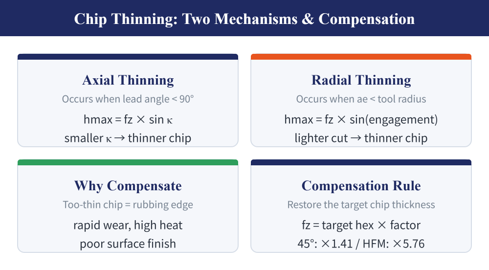
Keep the two terms separate: feed per tooth (fz) is the value you program; chip thickness is what the edge actually removes. They match only at a 90° lead angle with sufficient radial depth of cut. In every other case the chip is thinner than programmed — and an overly thin chip is bad news: the edge rubs instead of cutting, wear accelerates, heat rises, and surface quality suffers. Knowing how much thinner and compensating the feed is what this article is about.
2. Axial Thinning: the Smaller the Lead Angle, the Thinner the Chip
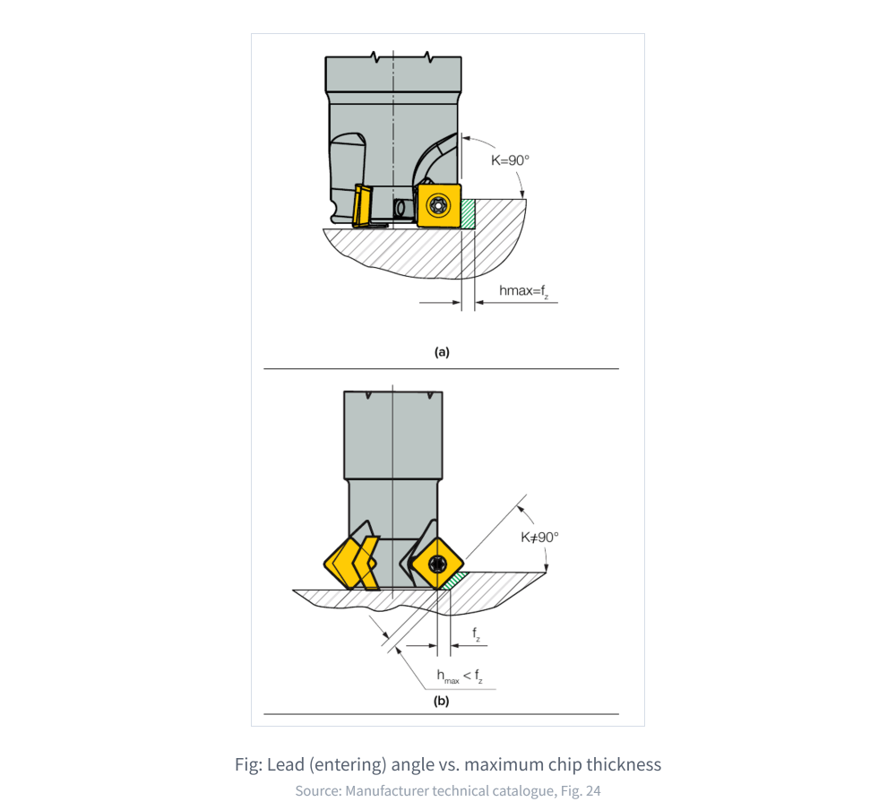
The first mechanism is axial chip thinning, governed by the lead (entering) angle κ. At 90°, maximum chip thickness (hmax) equals fz; as the angle decreases, the chip spreads over a longer edge and thins as hmax = fz × sin κ — and the effect steepens sharply at small angles:
| Cutting edge (lead) angle κ | Offset angle ψ | Max chip thickness (vs. fz) |
|---|---|---|
| 90° | 0° | 100% |
| 75° | 15° | 97% |
| 60° | 30° | 87% |
| 45° | 45° | 71% |
| 30° | 60° | 50% |
| 17° | 73° | 29% |
| 10° | 80° | 17% |
Values are calculated from the manufacturer catalogue formula, not measured by this site; always confirm cutting conditions with each brand's catalogue.
3. Radial Thinning: the Lighter the Cut, the Thinner the Chip
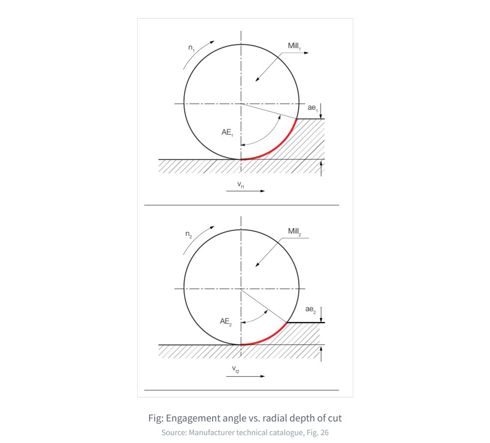
The second mechanism is radial chip thinning, governed by radial depth of cut (ae). In side milling or cavity work, whenever ae is smaller than the tool radius the engagement angle shrinks and the chip thins again:
hmax = fz × sin(AE) | AE = arccos((r − ae) / r) (r = tool radius)
Average chip thickness (estimate): hm ≈ fz × sin(AE / 2)
In light finishing both mechanisms often act at once. A rubbing edge not only wears fast — it also invites vibration; see What Is Milling Chatter: Causes, Diagnosis and Suppression for that side of the story.
4. Feed Compensation by Lead Angle
Compensation works as "fz = target chip thickness × factor": the smaller the lead angle, the higher the programmed feed must be to reach the same actual chip thickness. For starting values of speed and feed, see the End Mill Cutting Conditions and Parameter Calculation Guide:
| Lead angle | Feed compensation | Characteristics | Typical use |
|---|---|---|---|
| 90° | None needed (hex = fz when ae exceeds the radius) | Low axial force, radial force dominates | Square shoulders, thin walls, weak fixturing |
| 45° | fz = target hex × 1.41 | Thinner chip than 90°; raise feed for productivity | General face milling; less vibration at long overhang |
| 10° (high-feed cutter) | fz = target hex × 5.76 | Chip drastically thinned; very high feed per tooth possible | High-feed roughing (HFM) |
| Round insert | Depends on axial depth of cut (angle varies with depth) | Strongest edge; thinning varies with depth | Cavity roughing, heat-resistant alloys |
5. Worked Example
Given: a φ32mm cutter side-milling a shoulder at radial depth ae = 8mm. Target average chip thickness hm = 0.08mm. What fz should be programmed?
1) Take hm ≈ hmax / 2 → hmax = 0.16mm
2) AE = arccos((16 − 8) / 16) = 60°
3) fz = hmax / sin(AE) = 0.16 / sin 60° ≈ 0.185 mm/tooth
Conclusion: the programmed feed must be about 16% higher than the target chip thickness — proof again that fz and chip thickness are two different parameters.
Last updated: 2026-07-24
6. FAQ
Are feed per tooth (fz) and chip thickness the same thing?
No. They are equal only at a 90° lead angle with radial depth of cut no less than the tool radius; in every other case the real chip is thinner than fz. "Chip load" is often used loosely to mean feed per tooth, but strictly speaking it refers to chip thickness — be clear which parameter you mean before setting values.
If I switch to a cutter with a smaller lead angle, should I raise the feed?
Yes. To keep the same actual chip thickness, the smaller the lead angle, the higher fz must be: about ×1.41 for a 45° cutter and up to ×5.76 for a high-feed cutter (around 10°). Running a 45° cutter at a 90° feed rate simply produces thinner chips and wastes the productivity bonus.
What happens to the chip when radial depth of cut (ae) gets smaller?
Once ae is less than the tool radius, the engagement angle shrinks and maximum chip thickness reduces as hmax = fz × sin(engagement angle) — the lighter the cut, the thinner the chip. This radial thinning is independent of the axial thinning caused by the lead angle, and both often act together in light finishing passes.
How does chip thinning relate to high-feed milling (HFM) and high-speed milling (HSM)?
Chip thinning is exactly why these methods work: a small lead angle or a light radial depth presses the real chip thickness back into a safe range, allowing seemingly abnormal feeds per tooth without damaging the tool.
For the full reading guide on this topic, see Machining Calculation Reading Guide.
This article is part of End Mills: The Complete Guide - Know the Cutter, Choose It, Set the Conditions; Toolpaths Are Another Line; that guide shows how the whole topic fits together.









