
How to Read a Dial Indicator Spec Sheet: MPE Charts from JIS B7503 (Mechanical) and B7563 (Digital)
A dial indicator spec sheet carries a row of fields that mean nothing until someone explains them: hysteresis error, repeatability, 1/10 revolution indication error — and on digital models they change again into PMPE, EMPE, HMPE and RMPE. None of these are vendor inventions. Mechanical indicators follow JIS B 7503:2017, digital ones follow JIS B 7563:2021. This guide transcribes the maximum permissible error (MPE) tables of both standards cell by cell, then explains what each field governs and how the numbers are obtained. For values, go straight to sections 3, 4 and 7.
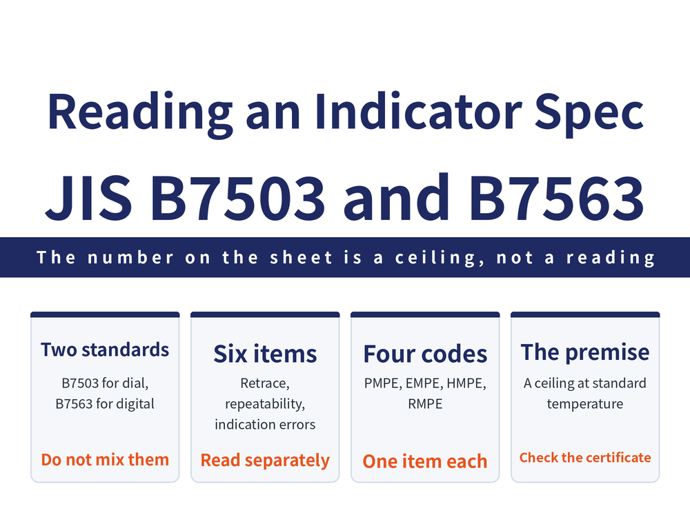
One point first: the numbers on a spec sheet are maximum permissible errors — upper limits, not the error this particular indicator actually shows. They promise "no worse than this", not "exactly this accurate". For how an indicator is mounted, clamped and zeroed, see Dial Indicator and Lever Indicator Usage Guide. For where the MPE system itself came from, see What MPE, EMPE and SMPE Mean on a Gauge Spec Sheet.
1. First Confirm Which Standard Applies to Your Indicator
Dial indicator spec sheets split into two families, and what decides it is the display type, not the physical size:
| Indicator type | Applicable standard | Error fields on the spec sheet |
|---|---|---|
| Mechanical (pointer and dial face) | JIS B 7503:2017 | Hysteresis error, repeatability, 1/10 rev, 1/2 rev, 1 rev, full measuring range indication error |
| Digital (numeric readout) | JIS B 7563:2021 | PMPE, EMPE, HMPE, RMPE, plus MPL |
The two standards use different field names, and their values are not interchangeable. Mechanical indicators have a notion of "revolutions" because one turn of the pointer equals a set travel; digital indicators have no gear revolutions and define the local range by number of measuring points instead.
2. What Each of the Six Mechanical Fields Governs
| Field | What it governs | Applies to |
|---|---|---|
| Full measuring range indication error | Difference between max and min error over all forward and return points | Sub-one-revolution and multi-revolution types |
| 1/10 revolution indication error | Largest difference between adjacent 1/10 rev points from start to 2 rev | Sub-one-revolution and multi-revolution types |
| 1/2 revolution indication error | Largest difference within each 1/2 rev span from start to 5 rev | Multi-revolution type |
| 1 revolution indication error | Largest difference within each 1 rev span from start to 10 rev | Multi-revolution type |
| Hysteresis error | Largest difference between forward and return readings at the same point | Sub-one-revolution and multi-revolution types |
| Repeatability | Largest spread of 5 readings taken by pressing the tip in at any position | Sub-one-revolution and multi-revolution types |
There is also measuring force, which governs not the reading but the force the tip applies to the workpiece; its permissible limit is coded MPL.
3. MPE for Indicators 50 mm and Larger in Bezel Diameter (JIS B 7503:2017)
The table below is transcribed from JIS B 7503:2017, in µm, graded by graduation and measuring range. To use it: find your graduation (0.01 / 0.005 / 0.001), then your measuring range row.
| Graduation (mm) | Measuring range (mm) | Hysteresis | Repeatability | 1/10 rev | 1/2 rev | 1 rev | Full range |
|---|---|---|---|---|---|---|---|
| 0.01 | 1 and under | 3 | 3 | 5 | 8 | 8 | 8 |
| 0.01 | over 1 to 3 | 3 | 3 | 5 | 8 | 9 | 10 |
| 0.01 | over 3 to 5 | 3 | 3 | 5 | 9 | 10 | 12 |
| 0.01 | over 5 to 10 | 3 | 3 | 5 | 9 | 10 | 15 |
| 0.01 | over 10 to 20 | 5 | 4 | 8 | 10 | 15 | 25 |
| 0.01 | over 20 to 30 | 7 | 5 | 10 | 12 | 15 | 30 |
| 0.01 | over 30 to 50 | 8 | 5 | 10 | 12 | 15 | 40 |
| 0.01 | over 50 to 100 | 9 | 5 | 12 | 17 | 20 | 50 |
| 0.005 | 5 and under | 3 | 3 | 5 | 9 | 10 | 12 |
| 0.001 | 1 and under | 2 | 0.5 | 2 | 3.5 | 4 | 5 |
| 0.001 | over 1 to 2 | 2 | 0.5 | 2 | 4 | 5 | 7 |
| 0.001 | over 2 to 5 | 3 | 1 | 3.5 | 5 | 6 | 10 |
One pattern stands out: the longer the measuring range, the wider the full range indication error (from 8 µm to 50 µm across the 0.01 graduation rows), while hysteresis and repeatability barely move. Long travel is a question of accumulated gear error; measuring the same point twice is a different question.
4. MPE for Bezels Under 50 mm and Back Plunger Types (JIS B 7503:2017)
Small bezels and back plunger types have their own table, with wider permissible values throughout. Also transcribed from JIS B 7503:2017, in µm.
| Graduation (mm) | Measuring range (mm) | Hysteresis | Repeatability | 1/10 rev | 1/2 rev | 1 rev | Full range |
|---|---|---|---|---|---|---|---|
| 0.01 | 1 and under | 4 | 3 | 8 | 11 | 12 | 15 |
| 0.01 | over 1 to 3 | 4 | 3 | 8 | 11 | 12 | 16 |
| 0.01 | over 3 to 5 | 4 | 3 | 8 | 12 | 14 | 18 |
| 0.01 | over 5 to 10 | 5 | 3 | 9 | 12 | 14 | 20 |
| 0.005 | 5 and under | 3.5 | 3 | 6 | 9 | 10 | 12 |
| 0.002 | 1 and under | 2.5 | 1 | 2.5 | 4.5 | 5 | 6 |
| 0.001 | 1 and under | 2 | 1 | 2.5 | 4 | 4.5 | 5 |
At the same 0.01 graduation and 1 mm measuring range, a large bezel is allowed 8 µm over the full range and a small one 15 µm — close to double. A small dial face is not only harder to read; its permissible error is wider to begin with.
5. Three Notes to Read Before the Tables
JIS B 7503:2017 attaches three notes to those tables. Miss any one of them and the numbers above can be misapplied:
| Note | Content |
|---|---|
| Note 1 | For sub-one-revolution indicators, arbitrary 1/2 rev and 1 rev indication errors are not specified |
| Note 2 | MPE values apply at the standard temperature of 20°C defined in JIS B 0680 |
| Note 3 | Unless the manufacturer specifies otherwise, the indicator must meet MPE and the measuring force limit MPL at every position in the range and in every attitude |
Note 3 is the one most often overlooked in practice: with nothing specified, the indicator must hold spec mounted sideways or upside down as well. Conversely, if the manufacturer does specify an attitude in the catalogue, the spec table holds only in that attitude.
6. The Four Letters on Digital Indicators (JIS B 7563:2021)
Digital indicator spec sheets use four abbreviations instead, defined in JIS B 7563:2021:
| Code | Full term | How it is measured |
|---|---|---|
| PMPE | Partial measuring range forward indication error | At least 6 points including the start, within 50 times the resolution |
| EMPE | Entire measuring range forward indication error | At least 11 points including start and end, and must include the PMPE points |
| HMPE | Hysteresis error | Press the tip in 0.1 mm or more at the end, then read the return direction at the same points |
| RMPE | Repeatability | Five return-direction actuations at any position, both brisk and gentle |
| MPL | Measuring force permissible limit | Read force at start and end; take max, min and the forward/return difference at one point |
The "partial measuring range" is not a span the vendor picks freely — it equals the resolution multiplied by 50. A 0.001 mm model gives 0.05 mm, and that conversion rule is written into the standard.
7. MPE Table for Digital Indicators (JIS B 7563:2021)
The table below is transcribed from JIS B 7563:2021, in µm. It groups by resolution, fixes the partial measuring range for each group, then grades by measuring range.
| Resolution (mm) | Partial range (mm) | Measuring range (mm) | PMPE | EMPE | HMPE | RMPE |
|---|---|---|---|---|---|---|
| 0.01 | 0.5 | 30 and under | 20 | 20 | 20 | 20 |
| 0.01 | 0.5 | over 30 to 100 | 40 | 40 | 20 | 20 |
| 0.001 | 0.05 | 30 and under | 3 | 3 | 3 | 2 |
| 0.001 | 0.05 | over 30 to 100 | 5 | 5 | 3 | 2 |
| 0.0005 | 0.025 | 30 and under | 3 | 3 | 3 | 2 |
| 0.0005 | 0.025 | over 30 to 100 | 5 | 5 | 3 | 2 |
The original table merges "15 and under" with "over 15 to 30", and "over 30 to 60" with "over 60 to 100"; the rows above expand those merges. The 0.001 and 0.0005 groups carry identical permissible values — that is how the original reads, not a transcription duplicate.
8. Reading the Two Standards Side by Side: Local and Global
The field names differ, but the skeleton is the same: check a short span first, then the whole span. The layering exists because the two kinds of error have different sources.
| Layer | Mechanical B 7503 | Digital B 7563 | What it catches |
|---|---|---|---|
| Local | 1/10 revolution indication error | PMPE | Consistency of graduation or signal over a short span |
| Mid | 1/2 rev and 1 rev indication error | (no counterpart) | Gear train accumulation over a few revolutions |
| Global | Full measuring range indication error | EMPE | Accumulated error over the whole spindle travel |
| Round trip | Hysteresis error | HMPE | Backlash and friction in the drive and guideway |
| Repeat | Repeatability | RMPE | Scatter when the same point is measured repeatedly |
Digital indicators have no "revolution" layer because there are no gear revolutions; they define local versus global by point count (6 points, 11 points) instead.
9. How the Numbers Are Obtained
Both standards use the fixed-point method for measurement and the floating-zero method for evaluation. The indicator is clamped on a support stand, the tip is moved in the forward direction, and the indication error is read at prescribed intervals.
The mechanical sampling interval thins out as travel grows: every 1/10 rev from start to 2 rev (every 10 graduations on sub-one-revolution types), every 1/2 rev from 2 to 5 rev, every 1 rev from 5 to 10 rev, every 5 rev from 10 to 50 rev, and every 10 rev beyond 50. At the end the tip is pressed in far enough to move the pointer 3 graduations or more, then the return direction is read at the same points.
Either reading order is allowed: align the pointer to a graduation and read the input from the reference instrument, or follow the reference movement and read the indicator. The two are equivalent in theory. Digital indicators follow the same principle.
10. The Spec Sheet Number Is a Limit, Not a Measurement
The MPE system inherits the ISO 14253-1 approach: a buffer of measurement uncertainty U sits between the specification zone and the conformance zone. The older "instrumental error" system had no such layer, and the specification zone was the conformance zone.
JIS B 7563:2021 explicitly cites the simple acceptance rule of ISO/TR 14253-6:2012: only when defined uncertainty conditions are met may the specification zone be treated as the conformance zone. In other words, "measured 19 µm against a 20 µm spec" is not automatically a pass — whether the U band is deducted depends on which acceptance rule is in force. For that history, see What MPE, EMPE and SMPE Mean on a Gauge Spec Sheet.
11. Attitude, Measuring Force, and What the Inspection Certificate Covers
Indicators are used in three attitudes: upright (tip down), horizontal (spindle level) and inverted (tip up). With the spindle level or the tip up, measuring force is lower than with the tip down — gravity no longer helps return the spindle and may pull against it. Always confirm the action before use, and confirm the pointer or digital display has returned to zero. Some models do not support all three attitudes, so check the product page.
One related purchasing detail is vendor practice, not a requirement of the standard: Mitutoyo inspects its finished digital indicators in the vertical attitude and supplies an inspection certificate; calibration results for the horizontal or inverted attitude are issued at extra charge by that company. Other brands may handle this differently, so ask before ordering. For related height measurement specifications, see Height Gauge Usage Guide.
12. Frequently Asked Questions (FAQ)
Q: The sheet says 15 µm over the full range. Does my indicator actually have 15 µm of error?
No. That is a maximum permissible error, an upper limit meaning "no worse than this", and individual units are usually better. It also applies at the 20°C standard temperature defined in JIS B 0680; shop temperatures away from that add thermal effects of their own.
Q: Can I compare the mechanical 1/10 revolution error with digital PMPE?
They sit at the same conceptual layer but the values are not directly comparable. Both describe consistency over a short local span, yet the span is defined differently: 1/10 of a pointer revolution for mechanical, 50 times the resolution for digital. Different sampling spans make the numbers non-comparable.
Q: Why do small bezel indicators get a wider permissible error?
JIS B 7503:2017 splits indicators into bezels 50 mm and larger and bezels under 50 mm (including back plunger types), and the latter table is wider throughout. At 0.01 graduation and a 1 mm range, the full range indication error is 8 µm versus 15 µm. Choose bezel size and accuracy requirement together.
Q: Does the spec still hold if the indicator is mounted sideways or inverted?
Under Note 3 of JIS B 7503:2017, unless the manufacturer specifies otherwise the indicator must meet MPE and the measuring force limit at every position in the range and in every attitude. If the catalogue does specify an attitude, the spec holds only there, and some models do not support all three attitudes at all.
This article is part of Precision Measurement Complete Guide: Ask What You Are Measuring First, Then Pick the Instrument; that guide shows how the whole topic fits together.









