
Drilling Inclined and Irregular Surfaces: Two Feed Reduction Charts and Four Countermeasures
Drill into an inclined, concave or irregular surface and the drill gets pushed off line and the edge chips. How much to cut the feed is not a guess — the manufacturer gives two rule charts, and the numbers differ: one set for indexable drills, another for solid carbide and exchangeable-head drills. This article keeps them apart and adds pilot hole limits, a runout threshold and three reground point forms.
1. Why a drill wanders on a slope
When the drill first touches a slope, the two cutting edges do not engage at the same moment. The radial reaction on the side that lands first has nothing on the opposite side to cancel it, so the whole drill is pushed sideways. At best the hole position drifts and the axis leans; at worst the drill breaks. Concave and irregular surfaces are variations on the same mechanism: asymmetric contact means unbalanced radial force.
There are only two families of countermeasure: 1 cut the feed, so the unbalanced phase is shorter and the force lower; 2 change the point geometry so the force is redistributed. Sections 2 to 5 cover the first, section 6 the second. For general drilling faults see the drilling troubleshooting guide.
2. Two feed charts — check which drill you are holding first
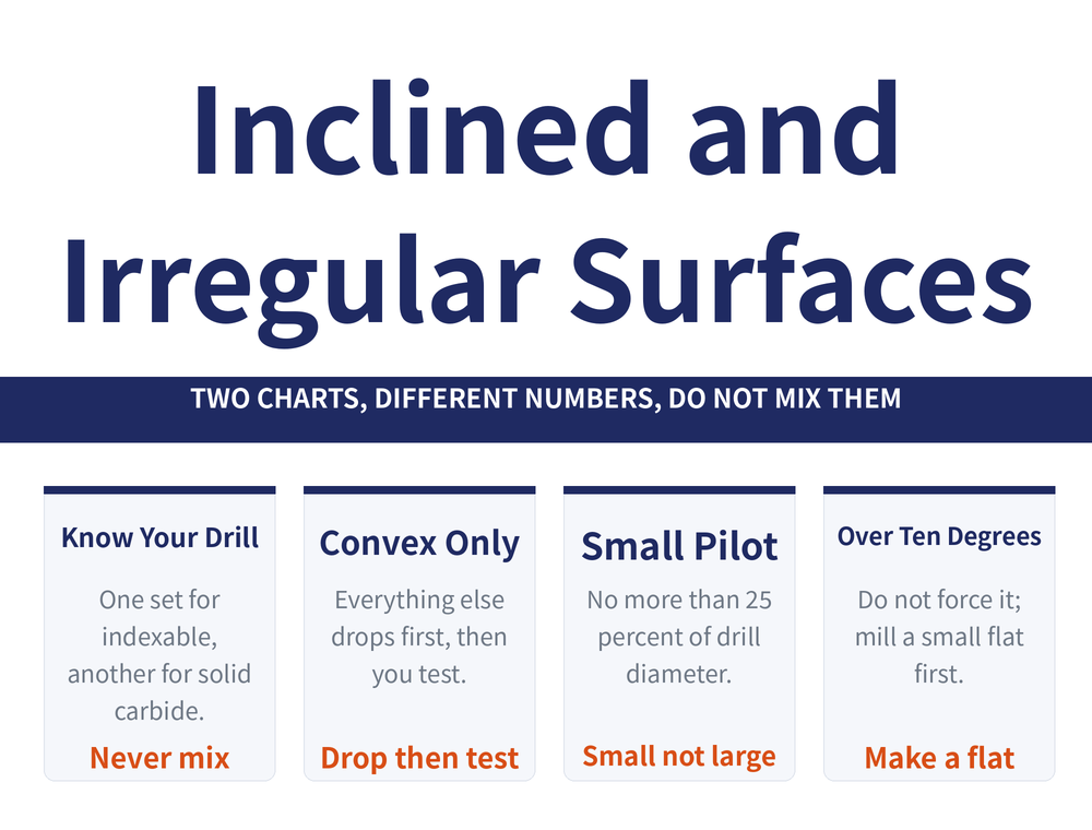
This is the key sentence of the article: the manufacturer gives one set of numbers for indexable drills and a different set for solid carbide and exchangeable-head drills, and they must not be swapped. Read the chart title before the numbers.
Chart one: indexable drills
| Surface | Feed reduction |
|---|---|
| Convex | Normally no reduction needed |
| Concave | Reduce to 1/3 of normal feed |
| Inclined (lead angle 2° to 89°) | Reduce to 1/3 of normal feed |
| Irregular | Reduce to 1/3 of normal feed |
This chart is easy to remember: only convex is exempt; everything else drops to a third first, then you test.
Chart two: solid carbide and exchangeable-head drills
| Surface | Condition | Feed reduction |
|---|---|---|
| Convex | Radius > 4x drill diameter, hole normal to the radius | May drill, at 50% of normal |
| Concave | Radius > 15x drill diameter, hole normal to the radius | May drill, at 25% of normal |
| Inclined | Angle 10° or less | Reduce to 1/3 of normal |
| Inclined | Angle over 10° | Entry not recommended, see section 4 |
| Irregular | — | Reduce to 1/4 of normal |
The two places the charts are most often confused: concave — a flat third for indexable, but radius-dependent and down to 25% for solid carbide; and irregular — a third for indexable, a quarter for solid carbide. These values are as given in the manufacturer's technical handbook, not measured by this site.
3. Keep the pilot hole small, not large
Faced with an irregular surface, the instinct is often to drill a generous pilot to flatten things out. The rule runs the other way: the pilot should be small rather than large, and no more than 25% of the drill diameter, or the drill will wander.
The reason is that an oversized pilot leaves the centre of the main drill unsupported, with only the outer edges cutting, so support is worse than before. Reducing the feed does widen the tolerance for the pilot, but that is widening tolerance, not permission to drill it larger. Hold the 25% line first, then spend feed on tolerance.
4. Over 10 degrees: do not force a solid carbide drill
The last row of chart two deserves its own section. On slopes steeper than 10 degrees, the manufacturer states plainly that solid carbide and exchangeable-head drills should not be entered; the correct answer is to mill a small flat first and drill from that flat.
This one is often skipped as over-cautious, but its cost differs from the rest: getting a feed reduction wrong misplaces the hole, while forcing this one chips the edge outright. An extra milling operation is cheaper than scrapping a solid carbide drill. The manufacturer adds two related limits: radial adjustment is not recommended on solid carbide drills because of the chipping risk, and an exchangeable-head drill cannot open an existing hole by boring. Neither applies to indexable drills, so again, do not transfer the practice.
5. The entry requirement for solid carbide: runout
Using a solid carbide drill on a difficult surface assumes the setup itself is true. Minimum tool runout is listed as one of the main criteria for success with solid carbide drills, and it should not exceed 0.02mm before close hole tolerance, good surface quality and stable tool life are even on the table.
| Item | Requirement |
|---|---|
| Holder TIR (total indicated reading) | Under 0.02mm |
| Temporary workaround | Rotate the drill or the collet 90° or 180° to find the lowest TIR position |
| Holder type | Hydro-mechanical, hydraulic or shrink-fit chucks |
A worn collet or holder will ruin an otherwise sound setup, so runout is a problem of the whole clamping chain, not of the drill. One more thing that is easily misread: with solid carbide and exchangeable-head drills, the first chips produced on entry are always long, and this is normal and causes no problem. Do not treat it as a chip evacuation fault and start changing parameters.
6. The regrinding route: three special point forms
If you have a twist drill rather than an indexable or solid carbide drill, the other route is regrinding the point so the forces redistribute. All three run at low speed with hand feed:
| Point form | Problem it solves | How it is ground |
|---|---|---|
| Inclined surface point | Radial reaction pushes the drill off line or breaks it | Ground to resemble a centre drill: enter to establish centre, then cut with the two outer edges; enter and exit slowly, keep speed moderate |
| Half hole point | A half-round hole, where a plain twist drill cuts badly off-balance | Ground concave with the two outer corners raised, run at low speed with hand feed; more or less than a true half hole changes the side load, so geometry needs adjusting, and a drill bushing helps |
| Ball-shaped universal point | Soft and hard material side by side, such as a soft bush in a hard hub, leaning the hole axis | The point is ground to a hemisphere, so the side load is spread over every direction on that sphere |
There is no specific cutting data for these three; the rule is simply "low speed, hand feed". For general twist drill regrinding, see how to regrind a drill.
7. Frequently asked questions
Q: Why are there two charts, and which one applies to me?
Because the two drill families fail differently. An indexable drill chips an insert; a solid carbide drill loses the whole edge, so their tolerance for unbalanced load is not the same and the manufacturer publishes two sets of numbers. Use the chart that matches the drill in your hand: chart one if it takes inserts, chart two for solid or exchangeable-head. The two differ most on concave and irregular surfaces, and the usual error is treating a solid carbide drill like an indexable one and not cutting the feed far enough.
Q: Why can the pilot hole not be a little larger?
Because once the pilot is large, the centre of the main drill is unsupported and only the outer edges cut, so the drill is less stable than before and wanders more easily. The rule is a pilot no larger than 25% of the drill diameter. Reducing the feed does widen the tolerance for pilot size, but that is widening tolerance rather than permission to open the pilot up. Hold the 25% line first and spend the feed reduction on tolerance.
Q: Is milling a flat really necessary above 10 degrees?
That rule is written for solid carbide and exchangeable-head drills, and the manufacturer states that entry is not recommended, with milling a small flat as the correct answer. The difference from the other rules is the cost: a wrong feed reduction misplaces a hole, while forcing this one chips the edge. An extra milling pass is cheaper than a scrapped solid carbide drill. With an indexable drill the applicable rule is chart one, lead angle 2 to 89 degrees, feed at one third.
Q: The first chips on entry are very long. Is chip evacuation failing?
No. The manufacturer notes specifically that with solid carbide and exchangeable-head drills, the initial chips produced on entry are always long, that this is normal, and that it causes no problem. Treating it as an evacuation fault and cutting the feed or changing parameters moves you away from a setting that was correct. Judge the chip form once the cut is steady, not in the moment of entry.
This article is part of Drill Bits: The Complete Guide - Start From Depth-to-Diameter, Then Pick the Drill and Set the Conditions; that guide shows how the whole topic fits together.
Published: 2026-08-30|Last updated: 2026-08-30









