
Why a Finish Turning Pass Must Run the Contour in One Go: The Continuous Cutting Principle and Two Uses for a Parting Tool
Change tools halfway through a finishing pass, or lead in and out in the middle of the contour, and the workpiece surface often ends up with a mark on it — usually not because the tool is dull, but because the cutting force changed abruptly. This guide covers the continuous cutting principle for finishing toolpaths: the complete contour is produced by the final pass running continuously, with approach and retract positions placed elsewhere. The second half covers two uses for a parting tool: chamfering and parting off with one tool, and turning the outside diameter directly on one-off or small-batch work to avoid the error a second setup introduces.
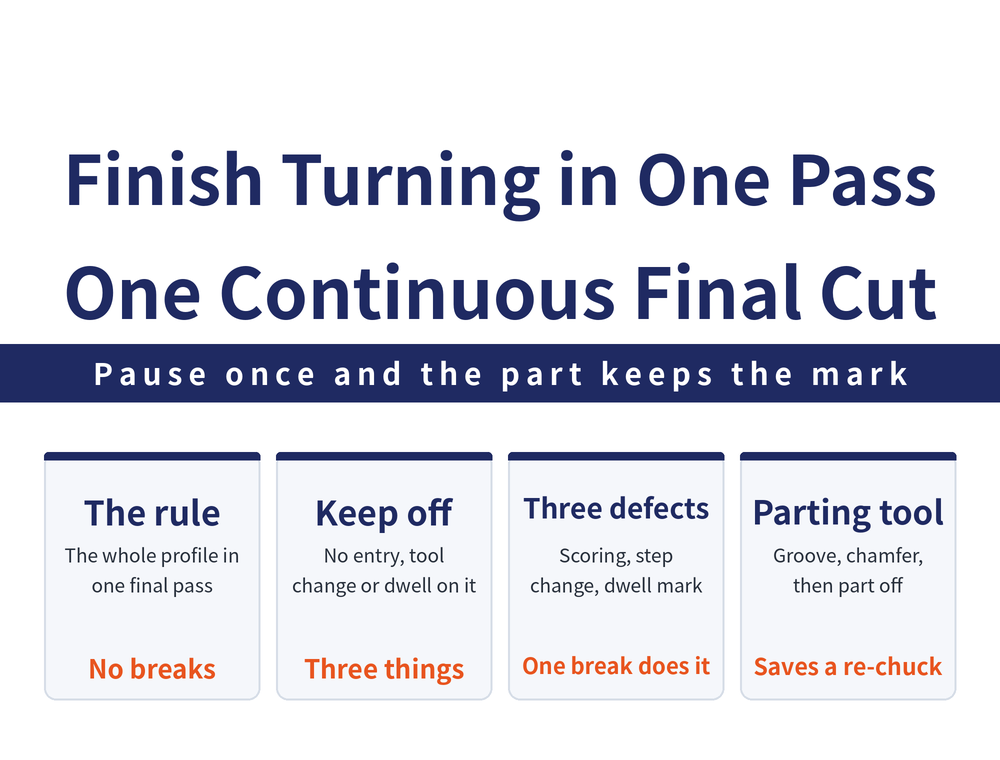
Same machine tool, same insert — a different finishing path arrangement gives a different surface. For toolpath planning as a whole, see How to Plan a Turning Toolpath. This article covers only the continuity of the finishing pass, plus two path techniques using a parting tool.
1. The Principle Itself: The Complete Contour Comes From One Continuous Final Pass
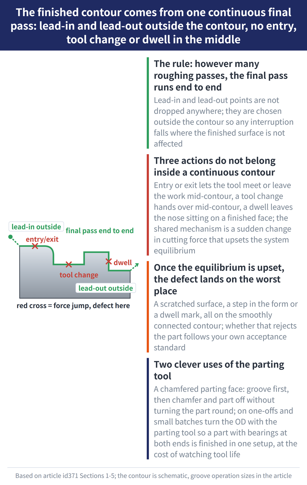
When laying out a finishing toolpath of one pass or several, the complete contour of the part should be produced by the final pass, cutting continuously. However many roughing and semi-finishing passes came before, the pass that produces the surface runs from one end of the contour to the other.
The requirement that goes with it: the approach and retract positions of the tool must be placed thoughtfully. Entry and exit points are not dropped wherever convenient; they go outside the contour, so any interruption happens where it cannot affect the finished surface.
2. Three Actions That Do Not Belong Inside a Continuous Contour
The principle in reverse is more concrete: as far as possible, do not schedule a lead in and out, a tool change or a dwell inside a continuous contour.
| Action to keep out of the contour | What it does mid-contour |
|---|---|
| Lead in / lead out | The tool first touches the workpiece, or leaves it, partway along the contour |
| Tool change | Cutting is interrupted partway along and handed to another tool |
| Dwell | Feed stops partway along and the tool tip lingers on the machined surface |
All three share one mechanism: the cutting force changes abruptly and upsets the equilibrium of the machining system. ⚠ The original teaching material lists the three together under a single attribution and does not separate out how their mechanisms differ; this article does not infer that on its behalf (not stated in the source).
3. Three Defects That Follow Once the Equilibrium Is Upset
Once equilibrium is lost, the defect lands on the smoothly connected contour — the stretch you least want trouble on:
| Defect | How it shows up |
|---|---|
| Surface scoring | Marks scored into the smoothly connected contour surface |
| Abrupt shape change | The contour becomes discontinuous in form at the point of interruption |
| Dwell tool marks | A ring of tool marks left where the tool lingered |
⚠ The original teaching material only names these three; it gives no method of identification and no quantified limits (not stated in the source). Whether they are grounds for rejection is for your own acceptance standard.
4. Parting Tool Use One: Groove First, Then Chamfer and Part Off
Now the two special toolpaths. The first: on parts where the parted face carries a chamfer requirement (common in batch turning), a parting (grooving) tool can do the chamfering and the parting off in one, so the part need not be turned round.
The method is to cut a groove to the process dimension first; the example given in the material is 4 mm × φ32 mm. That one groove buys three things at once:
| What grooving first does | What it solves |
|---|---|
| Makes the chamfer convenient | Chamfer and parting off are done with one tool in one setup |
| Reduces prolonged friction | Shortens how long the tool rubs when parting a larger-diameter blank |
| Helps chip evacuation | Chips get out more readily during the parting cut |
Choosing the insert and holder for the parting tool is a separate matter; see How to Read an ISO Turning Insert Code.
5. Parting Tool Use Two: Subprograms for Rolls, Direct OD Turning on Small Batches
The same parting tool has two further uses, neither a default approach; each holds only under specific conditions:
| Situation | Method | Condition and benefit |
|---|---|---|
| Machining roll-type workpieces | Program the parting tool's feed in all three directions into a subprogram, and complete the roughing by calling it | A repeating path is packed into one block of program and called again and again |
| One-off or small-batch work | Turn the outside diameter of the workpiece with the parting tool directly | Conditional on tool life being assured; suits workpieces that take bearings at both ends and carry a tighter concentricity requirement, and avoids the error a second setup introduces |
The reasoning behind the second one is direct: on a part that takes bearings at both ends, re-clamping adds one more concentricity risk; finish it in a single setup and that error source is gone. The price is that a parting tool was not designed to turn an outside diameter, so tool life is on you.
6. Where This Article Stops: Three Topics Covered Elsewhere
Several neighbouring topics on finishing paths have articles of their own:
| Topic | Where to read it |
|---|---|
| Infeed direction, quadrant reversal and the tool digging in | How to Prevent a Turning Tool From Digging In |
| Toolpath definition, the four principles, lead-in and retract methods | How to Plan a Turning Toolpath |
| Converting between speed, feed and cutting speed | Turning Machining Formulas |
One further note: figures 3-13(c) and (d) in the original material do mark the start and end of the parting tool's tool-position point during chamfering and parting off, but they are shown only as schematics, with no coordinate values given, so no tool-position coordinates are provided here (not stated in the source).
For the full reading guide on this topic, see Turning Toolpaths: The Complete Guide.
7. Frequently Asked Questions (FAQ)
Q: Does a finishing pass really have to cover the whole contour in one go?
The principle is that the complete contour is produced by the final pass cutting continuously. You may take as many roughing and semi-finishing passes as you like beforehand, but the pass that produces the surface should run through with no lead in and out, tool change or dwell.
Q: Where should the approach and retract positions go?
Outside the continuous contour. The principle asks only that they be placed thoughtfully, so that the tool touching and leaving the workpiece does not fall on the finished smooth surface; how far away is far enough is not given as a figure (not stated in the source).
Q: If the parted face needs a chamfer, must the part be turned round and machined again?
Not necessarily. A parting (grooving) tool can do both: cut a groove to the process dimension first (the material's example is 4 mm × φ32 mm), then chamfer and part off, with no second setup.
Q: Can a parting tool be used to turn an outside diameter?
On one-off or small-batch work, and provided tool life can be assured, yes. It suits workpieces that take bearings at both ends and carry a tighter concentricity requirement, and the gain is avoiding the error re-clamping for a second setup introduces.









