
How to Choose a Rough Turning Path: Rectangular, Triangular and Closed-Loop Compound Cycles Plus Five Concave Arc Routes
Removing the same amount of stock from the same bar gives very different cutting time, program length and finishing allowance depending on whether the tool travels a rectangular path, a triangular path or follows the part contour. This guide puts the three rough turning feed paths (rectangular, triangular, closed-loop compound cycle) into one comparison table, then ranks the five cutting routes for a concave arc surface by path length, programming difficulty and allowance uniformity — and marks every cell that has no reliable answer. To choose a path, go straight to the second and third tables.
This article covers only how the path geometry of the roughing stage is chosen. For the definition of a feed path, the four governing principles and the lead-in and retract methods, see How to Plan a Turning Feed Path.
1. A Rough Turning Path Is a Trade-off Between Three Things
Roughing has one job: take the excess stock off the bar and hand finishing a contour that is easy to cut. But with the same stock removed, the shape the tool tip traces changes the outcome a great deal.
Three things differ: the total length of the cutting path (which converts directly into cutting time and tool wear), the complexity of the program block format, and how uniform the allowance left for finishing is. The three rarely peak together, so choosing a path means choosing which one to give up.
The governing principle for roughing is to remove the excess stock in the least machining time, over the shortest machining path and with the steadiest cutting action, while striving for a uniform finishing allowance.
2. How Each of the Three Rough Turning Paths Travels
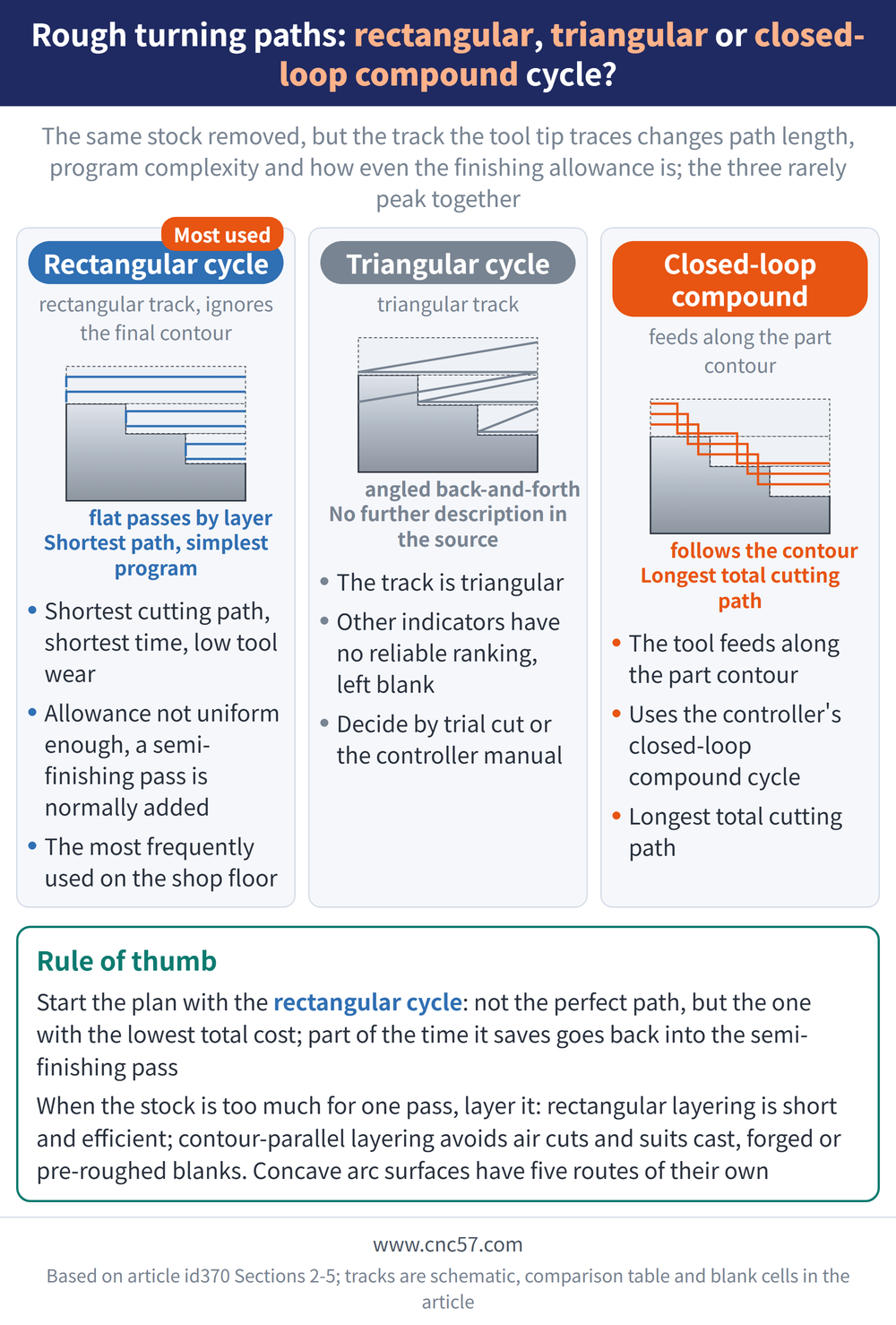
There are three feed paths in common use for roughing (or semi-finishing). All three are arranged with cycle functions; what differs is the track the tool tip traces:
| Type | How the path travels | How it is realised |
|---|---|---|
| Rectangular cycle | The track is rectangular and does not follow the final part contour | Arranged with the cycle function of the program |
| Triangular cycle | The track is triangular; no further description available | Arranged with the cycle function of the program |
| Closed-loop compound cycle | The tool is driven to feed along the contour shape of the workpiece | Arranged with the closed-loop compound cycle function of the controller (such as the G73 command) |
3. The Three-Type Comparison: Only the Rectangular Cycle Has Firm Answers
Across the six indicators below, only the two end points have an explicit comparison, the rectangular cycle and the closed-loop compound cycle. Every other cell has no reliable ranking, so it is left blank:
| Indicator | Rectangular cycle | Triangular cycle | Closed-loop compound cycle |
|---|---|---|---|
| Total cutting path length | Shortest | Longest | |
| Cutting time (rapid moves excluded) | Shortest | ||
| Tool wear | Low | ||
| Program block format | Simplest | ||
| Frequency of shop-floor use | Highest | ||
| Finishing allowance uniformity | Not uniform enough; a semi-finishing pass is normally scheduled |
For any blank cell, go by a trial cut on the machine or by the cycle notes in your own controller manual, and do not carry the rectangular cycle conclusions across.
4. Why the Rectangular Cycle Is Used Most on the Shop Floor
Three advantages stack up: the shortest cutting path converts directly into the shortest cutting time and low tool wear, and on top of that the program block format is the simplest. That is why the rectangular cycle is the first choice when a machining plan is drawn up.
The price is in the last row of the table. The contour left by rectangular-cycle roughing differs considerably from the final part contour, so the finishing allowance is not uniform enough. The remedy is not to go straight to finishing but to add a semi-finishing pass that evens the allowance out first.
Put another way, part of the time the rectangular cycle saves has to be given back to that semi-finishing pass. Before choosing it, check that the operation sheet has that pass on it.
5. When the Allowance Is Large: Rectangular Versus Contour-Parallel Layering
When the stock allowance is too large to clear in one pass, the cut has to be layered. Layered cutting feed paths come in two forms, and the choice takes in the stock shape, part rigidity and structural machinability, tool shape, production efficiency, and the cycle cutting functions the controller provides.
| Path form | Track | Characteristics | Main application |
|---|---|---|---|
| "Rectangular" layering | Roughing travels a track close to a rectangle | Shorter machining path, higher machining efficiency, convenient to program | |
| "Contour-parallel" layering | Roughing and semi-finishing travel a track parallel to the workpiece contour | Longer path, but rapid moves during machining are avoided | Cast, forged or already rough-turned workpieces |
6. The Five Cutting Routes for a Concave Arc Surface
A concave arc surface is a separate question. Five cutting routes are in common use for roughing a concave arc surface, and only two of them have a travel description:
| Ref. | Route | Travel description |
|---|---|---|
| (a) | Concentric circle route | |
| (b) | Equal-radius arc route | The cutting arcs share one radius and are arranged by offsetting the centre |
| (c) | Unequal-radius arc route | Start and end points stay the same; the cutting arc radius is varied so the chordal difference changes |
| (d) | Trapezoidal feed route | |
| (e) | Triangular route |
7. The Five Concave Arc Routes Ranked on Four Indicators
The five routes rank indicator by indicator, but not every indicator is ranked all the way down. Whatever is left unranked is again left blank:
| Indicator | Ranking (best to worst) |
|---|---|
| Fewest program blocks | Concentric, unequal-radius arc and equal-radius arc tie for fewest; their order among themselves, and where trapezoidal and triangular sit, source does not state |
| Shortest cutting path | Concentric → unequal-radius arc → triangular → trapezoidal → equal-radius arc (equal-radius arc longest) |
| Simplest calculation and programming | Equal-radius arc → concentric → triangular → trapezoidal → unequal-radius arc (unequal-radius arc most laborious) |
| Highest metal removal rate and best cutting force distribution | Trapezoidal route is best; the relative order of the other four, source does not state |
| Most uniform finishing allowance | Concentric route is best; the relative order of the other four, source does not state |
8. How to Trade Off on a Concave Arc, and Why a Convex Arc Is Easier
None of the five routes wins across the board; every one trades one property for another.
The concentric route leads on both shortest cutting path and most uniform finishing allowance, at the price of losing to the equal-radius arc route on ease of calculation and programming.
The equal-radius arc route calls a subprogram to run the cycle, which makes programming the least work; but it has the longest cutting path of the five, and it is not listed as best for allowance uniformity either.
The trapezoidal route has the highest metal removal rate and the most reasonable cutting force distribution, so it is the one to pick where efficiency comes first.
One common misunderstanding to clear up: the five routes above are for a concave arc. Machining an external arc (a convex arc) is comparatively simple and can be done with concentric circles, equal-radius arc offsetting, rectangular cutting and similar methods, with no need to pick among these five.
9. Two Things Still to Decide After the Path Is Chosen
The path type decides only the shape the tool tip traces, not how deep it cuts. Whether the same rectangular path is run in two passes or five depends on the depth of cut and the allowance to be left for finishing; see How to Split Turning Depth of Cut and Finishing Allowance.
To convert cutting speed and feed into spindle speed, feed per minute and machining time, the formulas are in Turning Machining Formulas.
Back to the principle: in practice the rectangular cutting method paired with semi-finishing is what most shops use to clear the leftover corner stock and raise overall machining performance. The rectangular cycle is not the perfect path, it is the one with the lowest total cost.
For the full reading guide on this topic, see Turning Toolpaths: The Complete Guide.
10. Frequently Asked Questions (FAQ)
Q: Why is the rectangular cycle chosen for most roughing?
Because three advantages stack up: the shortest total cutting path, the shortest cutting time with low tool wear, and the simplest program block format. Together they make it the first choice when a machining plan is drawn up, and it is also the most frequently used on the shop floor.
Q: Does a rectangular cycle always need a semi-finishing pass?
The contour left by rectangular-cycle roughing differs considerably from the final part contour, so the finishing allowance is not uniform enough and a semi-finishing pass is normally scheduled to even it out rather than going straight to finishing. In practice most shops use rectangular cutting paired with semi-finishing to clear the leftover corner stock.
Q: Is the triangular cycle better or worse than the rectangular one?
Only the two end points, the rectangular cycle and the closed-loop compound cycle, have an explicit comparison. The triangular cycle is left unranked on most indicators, so the comparison table leaves those cells blank. To decide, go by a trial cut on the machine or by the cycle notes in your own controller manual.
Q: Which concave arc route should be chosen for efficiency?
Choose the trapezoidal feed route: of the five it has the highest metal removal rate and the most reasonable cutting force distribution. If the aim is instead a uniform finishing allowance and the shortest cutting path, choose the concentric route; if the least programming work, choose the equal-radius arc route that can be run from a subprogram call.









