
Slotted Wheels and Interrupted Grinding: Self-Sharpening, Heat and Slot Patterns by Machine
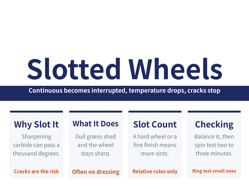
Cracking and annealing are the two things that ruin carbide and HSS tools during sharpening. Cutting a set number of angled slots into a vitrified wheel turns continuous contact into interrupted contact: the wheel self-sharpens, grinding temperature drops and the cracks stop. This covers the principle, how to set slot count and angle, the slot pattern for each machine type, and how to cut and check them.
1. Why sharpening carbide tools cracks them
Grinding carbide (cemented carbide) and high speed steel tools with an ordinary vitrified silicon carbide or aluminium oxide wheel can drive the contact zone past 1100°C instantaneously. Carbide is brittle and a poor conductor of heat, so the heat has nowhere to go and the insert readily develops cracks and crazing, cutting tool life sharply.
Picking the right abrasive and grit size will not fully remove this, because the root cause is that contact is continuous. Slotting attacks exactly that: machine a set number of slots at a sensible angle into the grinding face so that contact becomes interrupted rather than continuous.
The method was promoted by the Shanghai Tool Works, where more than 80 types of milling cutter were switched to it; its originator used it on the shop floor for years. An efficiency gain is also quoted, but the figure is written two contradictory ways in the same passage, so no multiplier is quoted here.
2. What slotting actually does: self-sharpening and heat
Self-sharpening means dull grains shed on their own so the wheel stays sharp while grinding. A wheel with good self-sharpening runs at higher grinding power and lower grinding temperature and is less likely to crack the insert; an unslotted wheel self-sharpens poorly. Slotting keeps the wheel sharp, and it is noted you can often grind without dressing the wheel.
Grinding carbide, slotted and unslotted sit side by side:
| What you observe | Slotted, interrupted | Unslotted, continuous |
|---|---|---|
| Colour at the contact zone | No visible red | Dull red |
| Insert after grinding | Surface not hot to the touch | Surface very hot |
| Residual stress and cracks | Low thermal stress, cracks unlikely | High surface residual stress, cracks likely |
| Overall | Far fewer cracked, annealed and reject inserts | Poorer grinding performance, higher temperature |
3. Setting slot count and angle
For slot count the guidance is relative rather than a universal number; the actual counts depend on machine type, covered in the next section:
| More slots when | Fewer slots when |
|---|---|
| Wheel is hard and self-sharpens poorly | Wheel is soft and self-sharpens well |
| Wheel-to-work contact area is large, grains dull fast | Contact area is small |
| Ground area is large | Ground area is small |
| Grinding high-titanium carbide | Grinding low-titanium carbide |
| Surface roughness requirement is tight | Surface roughness requirement is loose |
Angle and hand: in the cylindrical grinder context the specified slot angle is 25° to 35°, right hand, so that the axial force during grinding is pushed toward the machine spindle bearing. Other machine types have their own angles, listed below; do not carry one machine's figure over to another.
4. Slot patterns by machine type
| Machine | Slot count | Angle | Notes |
|---|---|---|---|
| Cylindrical grinder | 12–24, unequally spaced within 90° of circumference | 25°–35°, right hand | Keep depth and width equal on one wheel so it balances; unequal spacing kills the radial-force resonance that evenly spaced slots cause |
| Surface grinder | 24–36, slightly more than cylindrical | 20°–35° | Slot width 4–8mm; evenly spaced helical slots keep grinding smooth, free of vibration and chatter marks; round off the sharp corners of rectangular angled slots to stop edge break-out. Take the larger angle if the spindle is in poorer condition |
| Tool grinder (cup or bowl wheel) | 4–8, evenly spaced | 15°–20° rectangular angled slot | Hand of the slot follows wheel rotation; usually dry grinding |
| Tool grinder (dish wheel) | 8–16 rectangular slots; 4–8 for the 90° V slot | 15°–20° on the face | The working section is thin, so slots must be shallower and narrower; for face grinding the hand runs opposite to wheel rotation |
| Internal grinder | 4 slots at φ20mm, 6 at φ30mm, 8 at φ40mm; 4–16 in general | Increase the angle where there is a keyway | Slotting works best on bores above φ30mm; the larger angle removes the dip on either side of a keyway |
5. The three slot forms
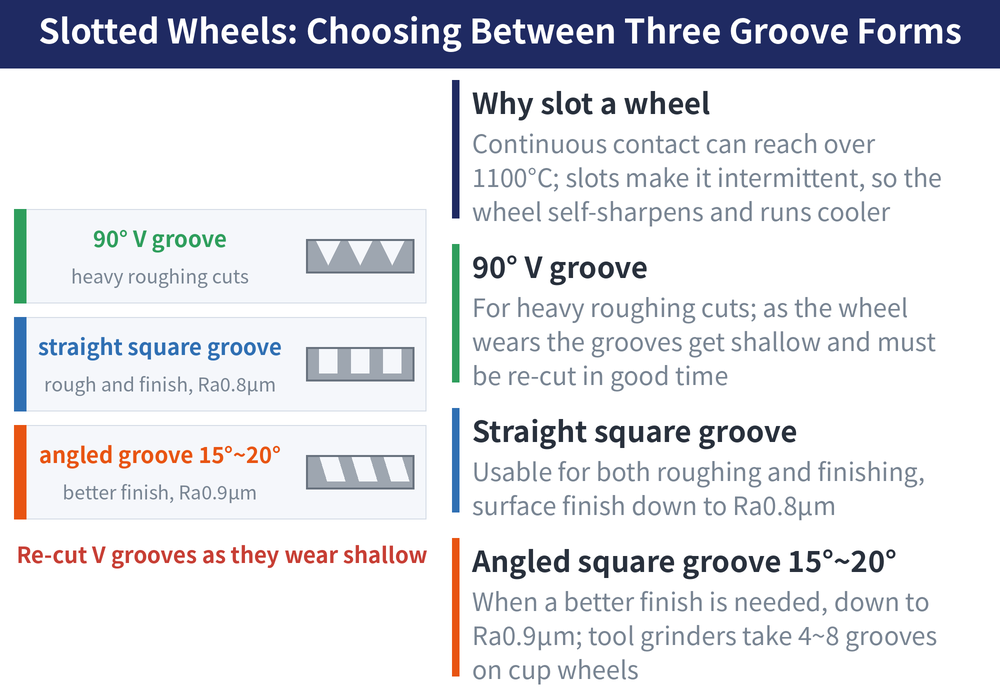
Cup and bowl wheels are slotted the same way, in one of three forms:
| Slot form | Where it fits | Roughness reached |
|---|---|---|
| 90° V slot | Roughing at heavy depth of cut | — |
| Straight rectangular slot | Roughing and finishing on one wheel | Ra0.8μm |
| Angled rectangular slot (15°–20°) | Where the finish matters more | Ra0.9μm and below |
The step most people miss with V slots: as the wheel wears the slots get shallower, and they must be deepened again in good time, or the inserts start cracking. A shallow slot is a return to continuous grinding.
6. Cutting the slots and checking the wheel
Hand slotting is done two ways. Clamp the wheel in a bench vice with wood or rubber packing between the jaws and the wheel, then cut the slots with a scrap cut-off wheel segment, a scrap saw blade or an abrasive stick. Small wheels for tool grinders can also be slotted freehand on a bench grinder, or mounted on the grinder spindle and steadied by hand.
Slotting modifies the wheel body, so the pre-run checks are stricter than for a new wheel:
| Check | What is specified |
|---|---|
| Balance | Balance a slotted wheel before use; an unbalanced wheel vibrates, leaves chatter marks on the work and can be dangerous in grinding. Small-diameter tool grinder wheels need not be balanced |
| Spin test | Spin for 2–3min in a wheel test rig at a surface speed of 35m/s |
| Ring test | Wheels under 150mm outside diameter can be tapped and judged by a clear ring |
The full balancing procedure and the diameter and speed thresholds are in Mounting and Balancing a Grinding Wheel. Slotting and dressing are two different ways of preparing a wheel; for dressing see Dressing a Grinding Wheel. If cracks or burn have already appeared, work backwards with Grinding Defect Troubleshooting.
7. FAQ
Q: Does a slotted wheel still need dressing?
Slotting exists to keep the wheel self-sharpening, and you can grind without dressing it. With V slots, though, deepen the slots again once wheel wear has made them shallow, or the inserts will start to crack.
Q: How many slots should I cut?
It follows machine type: 12–24 on a cylindrical grinder, 24–36 on a surface grinder, 4–8 on cup and bowl wheels for tool grinders, 8–16 rectangular slots on dish wheels, and on internal grinders 4 at φ20mm, 6 at φ30mm, 8 at φ40mm. Within a machine type, take the higher end when the wheel is hard, the contact area large or the finish requirement tight.
Q: Why are cylindrical grinder slots unequally spaced?
Evenly spaced slots set up a radial-force resonance, so on a cylindrical grinder the 12–24 slots are spread unequally within 90° of the circumference. On a surface grinder it is the opposite: evenly spaced helical slots keep grinding smooth and free of chatter marks. The two rules are different, so do not swap them.
Q: Is the spin test really necessary?
Yes. Slotting modifies the wheel body, and a 2–3min spin is required in a test rig at 35m/s surface speed afterwards. Wheels under 150mm outside diameter can also be tapped and judged by a clear ring, and the wheel should be balanced before use.
This article is part of Grinding Wheels and Machines: The Complete Guide - Reading the Wheel, Mounting It, Dressing It, and Tracing Defects; that guide shows how the whole topic fits together.
Published: 2026-08-16|Updated: 2026-08-16









