
Wheels for Tool Grinding: Abrasive, Shape and the Two Height Offsets
Plenty of shops own a tool grinder and still send tools out to be sharpened, or simply run them to scrap. This guide settles which wheel to use: how abrasive pairs with tool material, how to pick shape and diameter, and how far the wheel and the tooth rest sit from tool centre — because rake and clearance are exactly those two height offsets. A φ15 machine reamer works the whole thing through.
1. First split it: face or flank
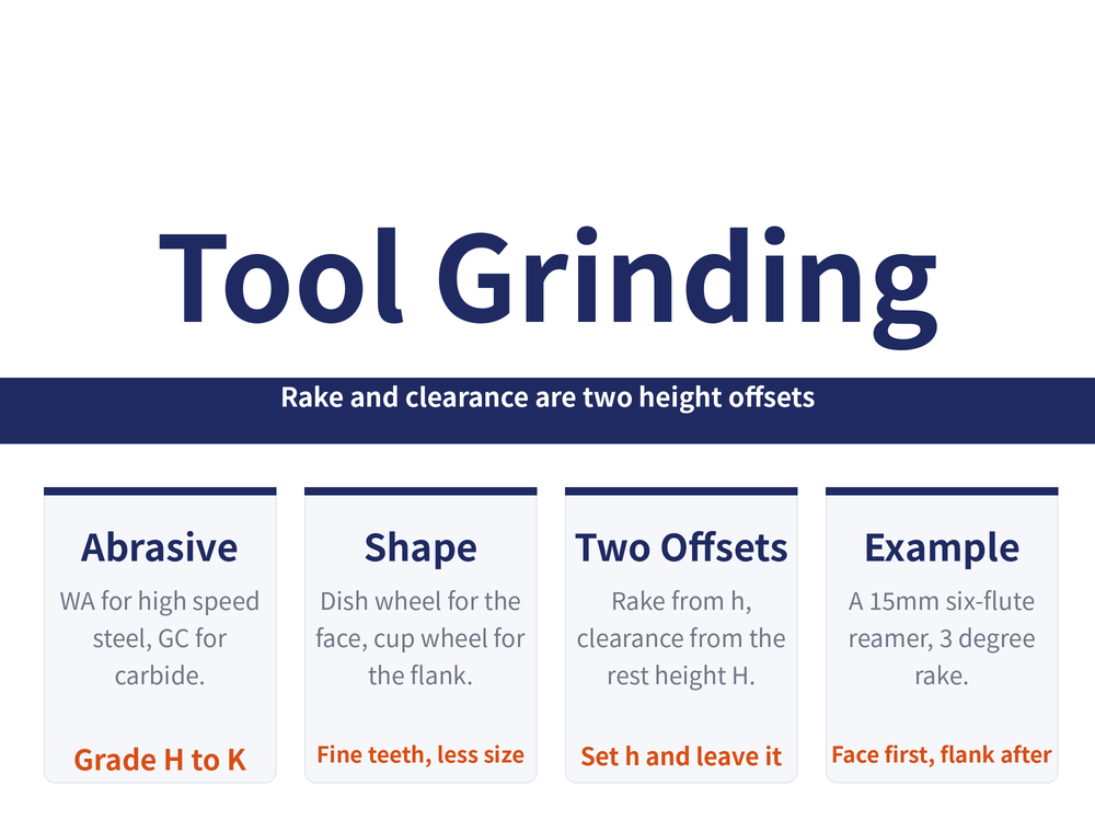
Every selection in tool grinding forks here: a dish or straight wheel for the face, a cup wheel for the flank. Abrasive follows the tool material, shape and diameter follow the feature being ground, and the setting position produces the angle. Keep the three apart and none of it is confusing.
For how a wheel marking is read, see Reading a Grinding Wheel Marking; for dressing a dull one, see Dressing a Grinding Wheel.
2. Abrasive: WA for HSS, GC for carbide
There is really only one rule: white aluminium oxide (WA) for high speed steel tools, green silicon carbide (GC) for carbide, with grades mostly between H and K and a vitrified bond. Below are the tools our customers regrind most; the source table runs to another twenty-odd rows covering hobs, shaper cutters and broaches, which are not reproduced here.
| Tool and feature | High speed steel | Carbide |
|---|---|---|
| Reamer, rake face | WA60~80 J~K V | GC100~120 H~J V / D80~150 |
| Reamer, taper and peripheral clearance | WA60~80 J~K V | GC100 H~J V |
| End mill, tooth face | WA80~120 J~K V | GC80~120 J~K V |
| End mill, tooth flank | WA80 J~K V | GC100~120 H V |
| Shell face mill, edges and clearance | WA46 H~J V | GC100 H V |
| Side and face cutter, peripheral face | WA60~80 H~J V | GC100 H~J V |
| Side and face cutter, clearances | WA60~80 J~K V | GC100 H~J V |
| Slitting saws and fine-tooth cutters | WA46~80 K V | GC100~120 H V |
3. Shape and diameter: three set-ups
| Feature | Shape and diameter | Suits |
|---|---|---|
| Face | Shallow single-bevel or dish type 1 (D1), φ150mm | Relieved cutters, reamers, end mills, face mills, angle cutters, broaches, side and face cutters |
| Face | Straight wheel (P) | Turning tools, drills, shaper cutters |
| Flank | Bowl (BW) or cup (B), φ75~125mm | Reamers, end mills, face mills, T-slot cutters, inserted-tooth cutters, side and face cutters |
Three practical notes: if the wheel cannot reach the flute root, drop to a φ50~75mm wheel; the rake of a helical or angled flute is ground on the bevel of the wheel (straight flutes take either the bevel or the flat); and on fine-tooth cutters reduce wheel diameter below φ100mm and set it below the tool centre line, or the neighbouring tooth gets damaged.
4. Setting: h gives the rake, H gives the clearance
The angles are not swung — they are two height offsets measured off tool centre.
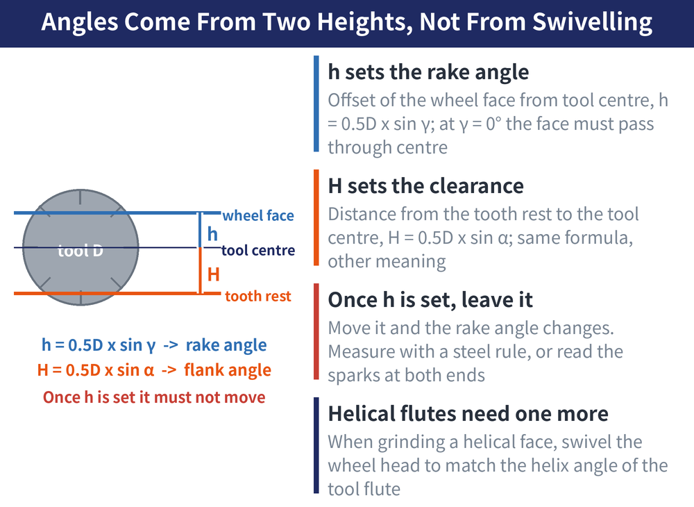
Wheel offset from tool centre h = 0.5D × sinγ, with D the tool diameter and γ the rake angle. At γ = 0° the extended grinding face passes through tool centre.
Tooth rest distance below centre H = 0.5D × sinα, with α the clearance angle.
🔴 Once h is set it must not be moved — move it and the rake changes. Measure h with a steel rule; on larger tools you can also judge by the sparks at both ends of the face, or by whether both ends are ground evenly. When grinding the face of a helical-flute tool, swing the wheelhead by an angle ω equal to the tool's helix angle, and the extended bevel must still pass through tool centre.
The rest changes with the tooth form: on straight coarse teeth keep it as close to the tip as possible; on straight fine teeth drop the wheel diameter below tool centre so the next tooth is not damaged; on helical flutes let the rest project 1~2mm past the wheel, no more, or it cannot reach the flute-root edge. Separately, swing the wheel spindle θ = 1°~2° so it grinds on one side only.
5. Worked example: a φ15 six-flute machine reamer
The tool is W18Cr4V2 at 60~63HRC, rake γo = 3°, cutting-tooth clearance αo = 10°, sizing-tooth clearance 8°, circular land f = 0.25mm. The wheel is WA, grit F46~F80, grade K, structure 5, vitrified bond; dish wheel dressed to an internal cone for the face, bowl or cup wheel with a hollowed end face for the flank, both dressed with a diamond point.
| Step | Setting |
|---|---|
| 1 Grind the face | Wheelhead swung 2° for single-edge contact; γo = 3° gives H = 0.39mm |
| 2 Grind diameter and tapers | Sizing diameter, back taper, cutting taper |
| 3 Sizing-tooth clearance | Wheel swung 1°~3° in plan; tooth rest H = 1.043mm below centre (for 8°) |
| 4 Cutting-taper clearance | Table swung 10°, tooth rest H = 1.303mm below centre |
While grinding the sizing teeth, keep the circular land at 0.25mm. These are settings from one documented example; for another size, recalculate with the two formulas in section 4. For the full reamer routine, see Regrinding a Reamer.
6. Frequently Asked Questions (FAQ)
Q: Can one wheel do both the face and the flank?
Not advisable. The face is ground inside the flute, using the thin rim of a dish wheel or the flat of a straight wheel; the flank is ground on the end face of a bowl or cup wheel. The shapes and the dressing differ, and forcing one to do both means missed surfaces or damaged neighbouring teeth.
Q: Are h and H the same thing?
Same form, different meaning. h is the offset of the wheel's grinding face from tool centre and it sets the rake; H is the distance of the tooth rest below tool centre and it sets the clearance. Both equal 0.5D times the sine of the angle — the angle is what changes.
Q: Why reduce wheel diameter on fine-tooth cutters?
Because with a small tooth pitch a large wheel touches the neighbouring tooth as well. Reduce it below φ100mm and set the wheel diameter under the tool centre line, and only the tooth being ground is in contact.
Q: Do carbide tools always need superabrasive wheels?
The table here gives conventional wheels (GC, green silicon carbide), which handle ordinary regrinding. Diamond or CBN comes in when you want higher output or a better ground finish, and selection for those has its own guide.
This article is part of Tool Regrinding: The Complete Guide — Decide Whether to Grind, Then Look Up How, With What, and How to Check; that guide shows how the whole topic fits together.
Published: 2026-08-18|Last updated: 2026-09-07









