
Lead-In and Overtravel Allowances: δ1 / δ2 Reference Values and the Accel-Decel Zone in Thread Turning
Where should the Z axis start feeding, and how much further must the tool travel after it breaks through? This guide lists the lead-in length δ1 and overtravel length δ2 reference values for hole-machining tools in two tables (drilling, boring, reaming, tapping × machined surface / blank surface), gives the d/3 + (3–8) expression for drilling overtravel, and explains why thread turning needs a separate acceleration and deceleration zone. To look up a value, go straight to the first table.
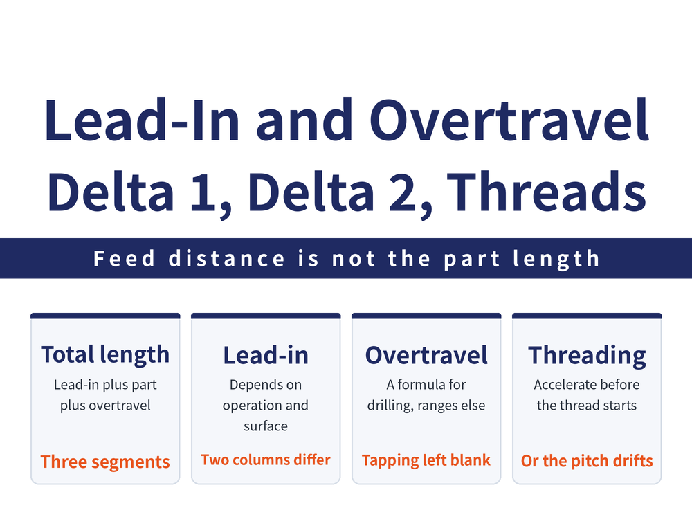
δ1 and δ2 are two stretches of travel that cut no useful material yet must always be allowed for. Too little and the tool crashes or leaves the feature unfinished; too much and every pass runs long. For how the toolpath itself is planned, see How to Plan a Turning Toolpath.
1. Where δ1 and δ2 Sit in the Working Cycle
The axial working cycle of a hole-machining tool normally has three stages: rapid approach → working feed → rapid retract. The middle stage is the one that costs time, and its length is not the machining length of the part.
Working feed distance = lead-in length δ1 (safety clearance / approach allowance) + workpiece machining length L + tool overtravel length δ2 (run-out allowance)
δ1 is the stretch between the end of rapid approach and the start of cutting; δ2 is the extra travel after breakthrough or after the tool bottoms out. Neither removes useful material, yet both are covered at working feed rate.
2. Lead-In Length δ1 Reference Values (Hole-Machining Tools)
The table below gives lead-in reference values in mm. Each operation is split by the starting surface: machined surface or blank surface.
| Operation | Machined surface δ1 (mm) | Blank surface δ1 (mm) |
|---|---|---|
| Drilling | 2–3 | 5–8 |
| Boring | 3–5 | 5–8 |
| Reaming | 3–5 | 5–8 |
| Tapping | 5–10 | 5–10 |
The blank-surface column is generally larger, because a blank surface is uneven and varies more in size. Tapping carries the same value in both columns; that is not an omission.
3. Overtravel Length δ2 Reference Values
Only three operations have a value that can be looked up, in mm. The drilling entry is not a fixed figure but an expression tied to hole diameter.
| Operation | Overtravel length δ2 (mm) |
|---|---|
| Drilling | d/3 + (3–8) |
| Boring | 5–10 |
| Reaming | 10–15 |
| Tapping | (left blank, see section 8) |
The blank tapping cell is deliberate, not an oversight; the reason is in section 8. Set that allowance from your controller's tapping cycle and the tool catalogue.
4. How to Read d/3 + (3–8)
Drilling overtravel δ2 = d/3 + (3–8) (d = drill diameter, in mm)
There are two terms: d/3 scales with diameter and (3–8) is a fixed margin independent of it. The larger the diameter, the further the tool must run out.
Confirm it by trial cutting on your own machine before relying on it. For the other turning calculations, see Turning Machining Formulas.
5. The Accel-Decel Zone in Thread Turning: δ1 In, δ2 Out
Thread turning needs δ1 and δ2 too, but for a different reason. A thread is formed by a fixed ratio between spindle speed and feed, and the feed axis must accelerate at the start and decelerate at the end.
If cutting begins on the very first revolution, that accel-decel zone lands on the thread form while the ratio is still unsettled, and the pitch goes out. So δ1 lets acceleration finish before the thread form starts, and δ2 puts deceleration after it ends.
The length depends on spindle speed, pitch and the controller's accel-decel behaviour; there is no general table for threads, so establish it by trial on the machine. For choosing an infeed method, see Thread Infeed Methods Explained.
6. When There Is No Table: the 2–5 mm Rule of Thumb
A general rule of thumb: δ1 is normally 2–5 mm, taking the larger value where accuracy demands it; δ2 may be somewhat smaller than δ1.
Its relation to the two tables above is straightforward: the tables are per-operation reference values for hole-machining tools, the rule is the default band when no table applies. Use the table where one exists, fall back to the band where none does.
7. δ1 Is Not the Rapid Approach Distance S
These two distances are often confused, but they belong to different stages of the cycle and cost different amounts.
| Item | Rapid approach distance S | Lead-in length δ1 |
|---|---|---|
| Traverse rate | G0 rapid | Working feed |
| Set from | Blank quality; at least greater than the stock allowance | Operation and starting surface; see table above |
| Time cost | Low | High, multiplied by feed time |
So S can be generous as long as it is safe, while δ1 should be taken from the table.
8. Notes on Using These Tables
Both tables are in mm; a blank cell means there is no reliable reference value, so measure on the shop floor rather than interpolating.
The tapping overtravel cell in section 3 is left blank because there is no reliable reference value for it.
On the machine, work from your controller's accel-decel behaviour, the tool catalogue and a trial cut. The values here are reference values, not an acceptance criterion.
For the full reading guide on this topic, see Turning Toolpaths: The Complete Guide.
FAQ
Q: How much lead-in length δ1 should be allowed?
The rule of thumb is 2–5 mm, taking the larger value where accuracy demands it. For hole-machining tools the table in section 2 is more precise: on a machined surface, drilling 2–3, boring and reaming 3–5, tapping 5–10; on a blank surface, drilling, boring and reaming all 5–8, tapping 5–10. All values in mm.
Q: Why is drilling overtravel an expression rather than a fixed value?
Because it scales with the drill: d/3 + (3–8), where d is the drill diameter in mm. It combines a term that scales with diameter and a fixed margin, so the run-out distance differs with hole size and a single figure would misrepresent it.
Q: Why must thread turning allow δ1 and δ2?
Because a thread is formed by a fixed ratio between spindle speed and feed, and the feed axis always has an acceleration and a deceleration phase. δ1 lets acceleration finish before the thread form starts and δ2 puts deceleration after it ends, so no cutting happens while the ratio is still unsettled and the pitch stays true.
Q: Why is the tapping cell in the overtravel table empty?
There is no reliable reference value for that operation, so the cell is left blank. Set tapping overtravel from your controller's tapping cycle and the tool catalogue.









