
How to Cut Rapid Travel in Turning: Start Point, Tool Change Point and Return-to-Zero
Within a turning cycle, every stretch where the insert is not touching the workpiece is rapid travel. It produces no chips yet still consumes machine time. This guide covers three ways to shorten it: separate the start point from the tool change point, move the tool change point closer to the workpiece (never with a boring bar in the turret), and switch to a simultaneous two-axis return to zero. Before adjusting any of those three points, look at the near-before-far rule of machining sequence — get the order wrong and the three techniques cannot make it back.
The Turning Technical Guide on this site currently holds 38 articles, and the subject of every one of them is which tool to use: insert standards, tool holder designations, regrinding, parting and grooving, cutting conditions. Across all 326 articles on the site, "rapid travel", "start point", "tool change point" and "return to zero" each return zero hits. The whole layer of how the tool travels is missing. That is the gap this article fills.
1. Rapid Travel Is the Non-Cutting Part of the Tool Path
The tool path is the entire route the tool covers from the moment it leaves the tool setting point (or the machine's fixed origin) until it returns there and the program ends. It holds two kinds of movement: the cutting route itself, and the non-cutting rapid travel of lead-in, exit, tool change and return.
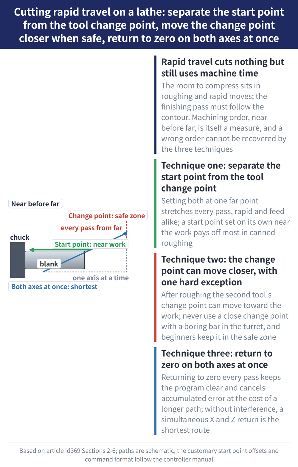
The room to compress sits in roughing and in rapid travel. The finishing pass essentially has to follow the part profile in order, so its route is dictated by the shape of the part and there is little to move. To save time, start with rapid travel.
For the full definition of the tool path and the four planning principles, see How to Plan a Turning Tool Path.
2. Near Before Far: Sequence Is Itself a Rapid Travel Measure
Far and near are measured relative to the tool setting point. Features close to the tool setting point are machined first, features further away later.
The wrong way: turning a stepped shaft in the order φ50 → φ45 → φ40 → φ35 lengthens the return to the tool setting point on every pass. Worse, it thins the part from the outset, so rigidity starts falling from the first cut, and burrs may form at the outer square corners of the steps.
The right way: run it the other way round, φ35 → φ40 → φ45 → φ50. Rapid travel is shorter, the rigidity of the blank or semi-finished part holds up longer, and cutting conditions improve with it.
3. Technique One: Separate the Start Point From the Tool Change Point
When roughing an outside diameter with a rectangular cycle, where the start point sits decides directly how far each of the four roughing passes has to travel.
The common practice is to put the start point and the tool change point at the same location, well clear of the blank, for the convenience of the later finishing tool change. The price is that both rapid travel and feed travel grow on every pass.
Pull the start point out of the tool change point and set it on its own, closer to the workpiece, and the same four roughing passes cut both kinds of travel noticeably. The same approach works in other cycles, such as facing cycles and thread turning cycles.
In practice the start point is generally set 1–2 mm larger than the outside diameter of the blank and 2 mm clear of the end face, which is both efficient and reasonably safe. This is a rough shop convention rather than an exact formula; set yours from the measured blank diameter and the clamping situation on your own machine.
4. Technique Two: The Tool Change Point Can Move Closer, With One Hard Exception
The tool change point may sit at the machine's fixed origin, at a floating origin, or at some position clear of the workpiece, depending on the operation.
To keep the turret from striking the part or the fixture during a change, the tool change point is almost always placed outside the part with a safety margin, and so usually ends up as far from the blank as the start point. The second tool then carries a correspondingly long rapid travel into its finishing pass.
Roughing has already removed the bulk of the stock, so the tool change point for the second tool can be moved closer. What decides it is what is mounted in the turret:
| Situation | How to set the tool change point |
|---|---|
| A boring bar is mounted in the turret | A close tool change point must not be used; collision risk |
| Stock removed by roughing, no long-reach tool in the turret | May be moved closer to the workpiece to shorten travel |
| Operator new to CNC machine tools | Safety before efficiency; keep it inside a safe zone |
5. Technique Three: Arranging the Return-to-Zero Route
When hand-writing a program for a more complex profile, some programmers send the tool back to zero (the machine origin) after every pass before running the next block.
The benefits are real: the program falls into clear blocks, it is easy to follow and hard to get wrong, and it clears the machine's accumulated error. The price is a longer tool path and lower productivity.
The middle course: where no machining interference occurs, use the command that returns the X and Z axes to zero simultaneously (G28 U0 W0). For the same return, the simultaneous two-axis route is the shortest.
6. The Three Techniques at a Glance
| Technique | Action | Condition and limit |
|---|---|---|
| Use the start point well | Separate it from the tool change point, close to the part | Most noticeable in roughing cycles |
| Place the tool change point well | Move it closer from the second tool onward | Never close with a boring bar mounted |
| Arrange the return to zero | Switch to a simultaneous two-axis return | No machining interference allowed |
| (Prerequisite) Near before far | Cut what is near the tool setting point first | Wrong order, and none of the three recovers it |
None of the three touches the cutting parameters; everything saved is non-cutting time. For how cutting speed and feed are calculated, see Turning Machining Formulas.
7. What This Article Does Not Cover
This article is about how far the path travels, not what shape it takes. Whether roughing runs a rectangular, a triangular or a closed compound cycle is a separate layer of decision.
How much lead-in to leave before the tool enters and how much overtravel to leave after it exits are values you can look up; see How Much Lead-In and Overtravel to Allow.
This is a strategy article and lists no G-code syntax. For the cycle and return commands mentioned here, follow the manual of the controller you run. As for how much time each technique saves, the source does not state any quantified figure; measure the benefit by comparing machining time statistics before and after on the same program on your own machine.
For the full reading guide on this topic, see Turning Toolpaths: The Complete Guide.
8. Frequently Asked Questions (FAQ)
Q: Are the start point and the tool setting point the same point?
Not necessarily. The tool setting point is the reference of the program coordinate system; the start point is where the cycle begins moving. They may coincide, and the technique here is precisely to separate them: set the start point closer to the workpiece and the rapid travel of the roughing cycle comes down.
Q: Does moving the tool change point closer risk a crash?
There is a risk, and what decides it is what sits in the turret. With a boring bar mounted, a close tool change point must never be used. Operators new to CNC machine tools are also advised to keep the tool change point in a safe zone and leave optimisation until the machine is familiar.
Q: Is returning to zero after every pass a bad habit?
Not a bad habit, a trade-off. Returning every pass keeps the program in clear blocks and clears accumulated error, at the cost of a longer path and lower output. The middle course is to keep the return but use the simultaneous X and Z return command, which is the shortest route for the same purpose.
Q: What share of a turning cycle is rapid travel?
There is no general share to apply. It follows from the shape of the part, how many tools are used and how the program is written; the shorter the part and the more tool changes, the higher the share. The most direct way to find your own is to subtract cutting time from total cycle time on the same program and compare.









