
Choosing a Taper Grinding Method: Cone Angle and Part Length Decide
There are four ways to grind a taper, and the choice is not made from the machine you happen to own. It is made from two things: how large the cone angle is and how long the part is. A small angle on a long face goes on the swivel table, a large angle on a short part goes on the swivel headstock, and only when neither works does the swivel wheelhead come in. Batch work dresses the angle onto the wheel instead. This article covers that split, the wheel diameter limit inside a taper bore, the three families of inspection, and where to look first when the taper measures wrong.
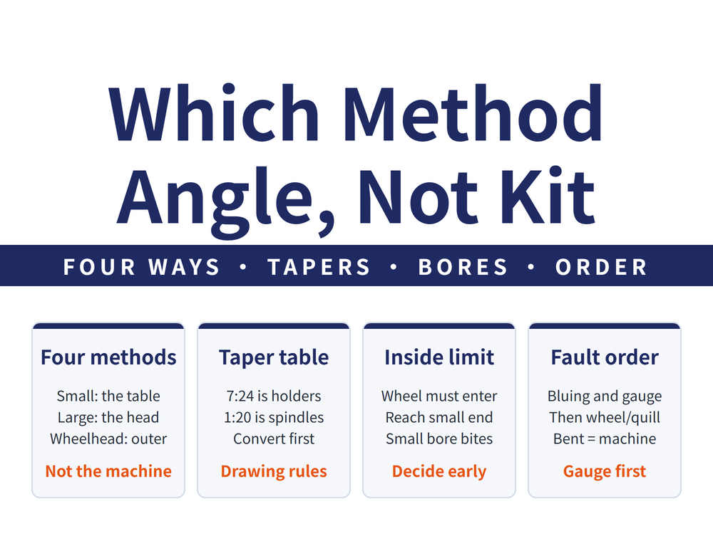
1. How the four methods divide up
Start from the cone angle and the part length, then look at the equipment. Reverse that order and you choose wrong:
| Method | Where it fits | Int / ext |
|---|---|---|
| Swivel the table | Small angle (generally under 18 deg), long taper face | Both |
| Swivel the headstock | Larger angle, shorter part, chuck can hold it | Both |
| Swivel the wheelhead | Large taper and long, when neither of the first two fits | 🔴 External only |
| Angle dresser | Batch work, taper not restricted | As dressed |
In one sentence: cone angle and part length choose the method, not the equipment.
The first two are the normal case. The other two are fallbacks for when the first two will not work, and each carries a clear cost.
2. Swivel wheelhead: external only, with two hard limits
It only comes up when the taper is both large and long, the table will not swivel far enough, and the part can only be held between centres so the headstock method is unavailable. The wheelhead swivels by the half cone angle.
Two hard limits must be settled before you start: only infeed is available because the table cannot traverse, so the taper face must be shorter than the wheel is wide - too narrow a wheel simply cannot reach the whole face. And because the table does not move, accuracy and surface finish are hard to improve, so this method is not often used.
3. The angle dresser: the batch answer
Here the wheel is dressed to a specific angle first, such as 45 or 60 degrees, and the taper is then ground by wheelhead infeed. The advantage is that the taper is not restricted, and neither wheelhead nor headstock has to be swivelled. The drawback matches the previous section: no traverse, so accuracy and finish are limited.
Its real value is in quantity. When a batch shares one taper, putting the angle on the wheel beats setting the machine for every part. For dressing methods themselves, see Dressing a Grinding Wheel: Choosing Turning, Crush or Grinding Method.
4. Common standard tapers at a glance
Before grinding you need to know what angle the taper on the drawing actually is. These are the common dedicated standard tapers:
| Taper C | Cone angle | Half angle | Where it is used |
|---|---|---|---|
| 1:50 | 1°8′45″ | 0°34′23″ | Taper pins, dowels, pin hole reamers |
| 1:30 | 1°54′35″ | 0°57′17″ | Shank mounted reamers and core drills |
| 1:20 | 2°51′51″ | 1°25′56″ | Machine tool spindle taper, tool shanks |
| 1:12 | 4°46′19″ | 2°23′9″ | Adapter sleeves for ball and roller bearings |
| 1:10 | 5°43′29″ | 2°51′45″ | Tapered shaft ends, combined load joints |
| 1:7 | 8°10′16″ | 4°5′8″ | Heavy machine centres, plug cocks |
| 1:5 | 11°25′16″ | 5°42′28″ | Easily parted taper joints, cone clutches |
| 7:24 | 16°35′39″ | 8°17′50″ | Milling arbor shank and mill spindle bore |
| 1:0.866 | 60° | 30° | Lathe centres, centre holes |
The 7:24 and 1:20 rows map directly onto tool holders: the 7/24 steep taper of the BT, NT and CAT family is the 7:24 row above. For the specification systems and how to select, see Tool Holder Taper Guide: BT, NT & Morse Taper (MT) and Spindle Taper Systems Overview: BT, HSK, Capto, SK, NT, CAT, MT. Values above are transcribed from the technical source; accept parts against the drawing and the current issue of the standard.
5. Internal tapers: wheel diameter is the constraint
For an internal taper, wheel diameter follows from the small end of the taper bore and the half cone angle - the wheel has to enter the bore and still reach the small end.
🔴 A small bore with a small half angle is where this must not be overlooked. The practical inference is that too large a wheel may miss the small end, or not go into the bore at all.
That is a calculation for the selection stage, not a discovery at the machine.
For symmetrical internal tapers that also need good concentricity, there is a quick and accurate sequence: grind the outer internal taper correctly, leave the headstock angle untouched, swing the internal wheel across, and grind the inner one. The part never leaves the machine and the headstock angle never moves, so the two tapers not only match in angle, their concentricity is high as well. For internal wheel and quill selection, see Why Internal Grinding Is the Hardest: Get the Wheel and the Quill Right First.
6. Inspection: three families, each with its place
| Method | How you judge | Where it fits |
|---|---|---|
| Universal bevel protractor | Light gap method; 2 min graduation | One off work, modest accuracy |
| Angle template | Template through centre, light gap | Batch work, modest accuracy |
| Taper gauge | Three lines of bluing, half a turn, read the contact | Close fits judged by contact area |
| Sine bar | Stack blocks to sin a = H/L, read two points on the line | External tapers, high accuracy |
Reading a sine bar is direct: with points a and b on the taper line, equal readings mean the angle is right; a higher than b means the angle is too large; a lower than b means too small. With a taper gauge the contact should sit toward the large end, and contact length is graded: high precision 85% or more, precision 80% or more, ordinary 75% or more.
⚠ A sine bar is not a sine fixture. A sine fixture holds the part at an angle while grinding a flat; the sine bar here is a separate gauge for measuring an external taper afterwards. The principle is shared - both set an angle from a centre distance and a block stack - but the use is not, so do not swap them.
Taper size is judged separately from angle, using the lines or steps on the gauge: with a plug gauge, both lines entering means the bore is too large; neither entering means too small; the first line in and the second out means it passes. With a ring gauge, the part end face must fall between the two step faces.
7. Taper measures wrong: suspect the measurement first
The order in this table is a practical inference from the causes (the causes and remedies themselves do not prescribe which to check first), but getting it backwards can cost you one wasted machine setting:
| Order | What to look at | What to do |
|---|---|---|
| 1 Measurement | Bluing too thick, gauge axis rocking | Bluing very thin and even, rotate within 30 deg |
| 2 Dull wheel | Finishing with a dull wheel; deflection shifts the taper | Dress often; spark out until sparking nearly stops |
| 3 Quill | Long slender taper bore, weak quill | Quill short and thick, narrower wheel, less finish stock |
| 4 Heat and oil | Local heating; excess slideway oil floating the table | Measure often in the first 1 to 2 hours; adjust oil |
The first row comes first because an inaccurate measurement leads to the table, headstock or wheelhead being set wrongly. Bluing laid on too thickly, or a gauge rocking as you check it, gives a false contact pattern and can pass a taper that is actually inaccurate as accurate. Measure accurately first, then lock the table, headstock or wheelhead.
8. A bent taper line is a different fault: hyperbolic error
An incorrect taper and a taper line that is not straight are two different defects and should not be diagnosed together. A bent line is not a wrong angle; the line itself is curved into a hyperbola.
There is exactly one cause: the wheelhead axis, or the internal wheel spindle axis, is not at the same height as the part axis.
And exactly one answer: repair or adjust the machine until the two axes are level. Parameters and wheels will not touch it.
Out of roundness follows the same diagnosis as an external cylinder. For how to check machine accuracy itself, see Grinding Machine Accuracy: Error-to-Defect Map and the Four Acceptance Tests.
9. Frequently Asked Questions (FAQ)
Q: Does taper grinding need a dedicated machine?
No. Three of the four methods run on an ordinary cylindrical grinder - swivel the table, the headstock or the wheelhead - the difference being only which part swivels. The choice comes from cone angle and part length, not from the equipment. An angle dresser, putting the angle on the wheel, is considered for batch work.
Q: Can the swivel wheelhead method grind an internal taper?
No, it grinds external tapers only, and that is its main difference from the swivel table and swivel headstock methods, which handle both. It also works by infeed alone, so the taper face has to be shorter than the wheel is wide or the whole face cannot be reached.
Q: The taper measures wrong. What do I do first?
Check the measurement before touching the machine (a practical order drawn from the causes). Bluing laid on too thickly, or a taper gauge rocking during the check, gives a false contact pattern and can pass a taper that is actually inaccurate as accurate. Apply bluing very thin and even and rotate within 30 degrees. Once you trust the reading, work through a dull wheel, quill stiffness, and machine thermal growth in that order.
Q: The taper line came out curved. Which parameter fixes it?
None of them. A curved taper line is hyperbolic error, and it has one cause: the wheelhead axis, or the internal wheel spindle axis, is not level with the part axis. The answer is to repair or adjust the machine so the two axes match. It is a separate defect from an incorrect taper and should not be diagnosed with it.
When an outside diameter will not come round, start with the centre holes: see Out of Round on the Cylindrical Grinder? Check the Centre Holes First.
This article is part of Grinding Wheels and Machines: The Complete Guide - Reading the Wheel, Mounting It, Dressing It, and Tracing Defects; that guide shows how the whole topic fits together.
Published: 2026-09-19|Last updated: 2026-10-24









