
Wiper Inserts in Turning: Double the Feed, Better Finish
In turning, the first thing that decides how good the surface is turns out to be the feed per revolution, not the spindle speed. A wiper insert carries an extra large-radius arc behind the main corner, wiping flat the marks left by the previous revolution. Its value is not appearance but the fact that it lets the feed be pushed up at the same surface quality.
1. Start with the Picture: How a Wiper Differs from a Conventional Insert
The wiper is a difference in geometry, and looking at the picture is faster than reading about it.
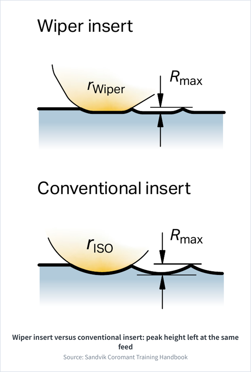
Manufacturer illustration (Sandvik Coromant Training Handbook). Wiper insert on top, conventional insert below. Look at the difference in height of the residual peaks on the right.
2. Why Theoretical Roughness Is Tied to the Feed
The surface left by turning is essentially a helical mark cut by the nose radius, one turn at a time. How deep that mark is comes down to fn (feed per revolution) and rε (nose radius).
Theoretical roughness (feed-mark peak-to-valley height): h ≈ fn² ÷ (8 × rε) × 1000 (μm)
h is the peak-to-valley height of the feed marks (Rt in the diagram above), not the Ra on the drawing; fn is the feed per revolution and rε is the nose radius. At fn 0.2 and rε 0.8, h is about 6.25 μm, while an Ra estimate (Ra ≈ fn² × 50 ÷ rε, per Seco technical data) gives about 2.5 μm. fn is a squared term, so it weighs far more than rε, and that is why the surface gets worse the moment the feed goes up.
3. The Two Traditional Routes Both Have a Price
To bring the roughness down, tradition offers only two routes.
| Traditional approach | Effect on the finish | What it costs |
|---|---|---|
| Reduce fn | A squared relationship, so even a small reduction shows clearly | Cutting time gets longer and finish turning becomes the bottleneck |
| Increase rε | A larger denominator brings the roughness down | Radial force rises and slender parts vibrate easily |
The table above gives general direction only. The actual result depends on the insert style and the cutting situation, so follow the catalogue or the relevant standard. Not measured by this site.
Each route sacrifices one side. For the trade-off on nose radius, see How to Choose the Turning Insert Nose Radius; for the remaining formulas, see Turning Machining Formulas.
4. How a Wiper Breaks That Trade-off
What a wiper does is very direct: behind the main nose radius it adds one or several wiper arcs of very large radius, and those arcs sit almost parallel to the workpiece surface.
The wiper section sweeps over the marks left by the previous revolution once more and shaves the peaks flat, which is the same as enlarging the effective nose radius without touching fn.
For reading the designation, see ISO Turning Insert Designation Guide. Wiper geometry is usually flagged by a suffix or a proprietary code, and the marking differs between makers.
The first four sections condense into three cards, and the two sections that follow are both about the third card.
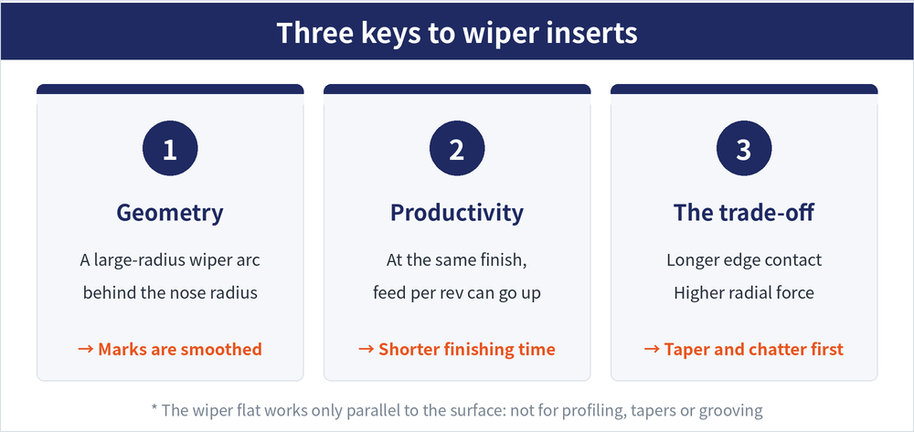
Compiled by this site. Left to right: the geometry, the gain, the price.
5. Two Ways to Use It: A Better Finish, or a Higher Feed
The same wiper insert supports two ways of working, and the only difference is where the margin it creates gets spent. In practice the second one is more common.
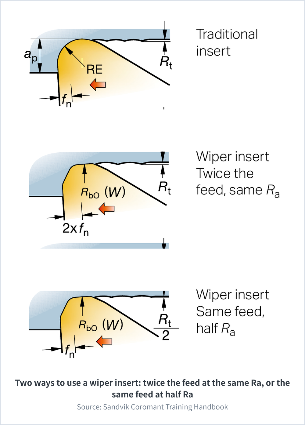
Manufacturer illustration (Sandvik Coromant Training Handbook). Look at the height of R t on the far right.
| Use | What you do | What you get | Where it fits |
|---|---|---|---|
| Keep the feed | Keep the original fn and simply change the insert | Same cycle time, better surface | The cycle time cannot be touched |
| Raise the feed | Raise fn until the surface comes back to its original level | Finish turning takes less time | Finish turning is the bottleneck |
| Split the difference | Raise only part of the feed | Both improve slightly | Ordinary rigidity |
General direction only. The actual result depends on the insert style and the cutting situation, so follow the catalogue or the relevant standard. Not measured by this site.
6. What Needs Watching Is Force and Rigidity
When rigidity is short, what shows up first is taper and vibration, not a worse surface.
| Item | Status | Notes |
|---|---|---|
| Radial cutting force | Watch out | Contact gets longer, so the radial component runs higher |
| Slender shafts and thin-walled parts | Watch out | They are easily pushed away and produce taper |
| System rigidity | Watch out | Clamping and holder rigidity have to be sufficient |
General direction only. The actual result depends on the insert style and the cutting situation, so follow the catalogue or the relevant standard. Not measured by this site.
7. Where It Does Not Apply
Every limitation below comes from the same sentence: the wiper section only works when it stays parallel to the surface.
| Situation | Conclusion | Reason |
|---|---|---|
| Profiling and contour turning | Not suitable | As soon as the contour changes it is no longer parallel |
| Angled faces and tapers | Not suitable | Any included angle kills the effect |
| Grooving and threading | Not suitable | There is no wiper section left to act |
| Roughing | No point | The surface is decided by the finishing pass |
| Depth of cut | It depends | Clearest at the small depths used in finish turning |
| Radius pairing | Per maker | The combination depends on the insert style |
General direction only. The actual result depends on the insert style and the cutting situation, so follow the catalogue or the relevant standard. Not measured by this site.
For reading taper, chatter marks and unstable dimensions, see Turning Troubleshooting Guide. The manufacturer illustrations in this article are reproduced from the Sandvik Coromant Training Handbook and remain the copyright of the manufacturer.
Last updated: 2026-10-12
8. Frequently Asked Questions (FAQ)
Q: Can I just fit a wiper insert and leave the parameters alone?
Yes, and that is the first use: the surface improves. To get the productivity benefit, though, the feed has to be raised and vibration and dimensions re-confirmed.
Q: How much can the feed actually be raised?
There is no universal factor; it depends on the insert style and the rigidity of the part. Work from the recommended range in the catalogue and confirm with a trial cut, and recalculate cutting speed, depth of cut and tool life at the same time — see the Turning Cutting Conditions Guide.
Q: Why can a wiper not be used for profiling?
The wiper section only works while it is parallel to the surface. Once the contour changes the angle changes with it, the wiping effect disappears, and the result can be worse than with a conventional insert.
Q: Can wiper inserts be used on slender shafts?
Only with care. Radial force is higher than with a conventional insert, so a slender part is easily pushed away and turns taper. Confirm the clamping and the vibration first, and only then talk about the feed.
For the full reading guides on this topic, see Surface Finish: A Complete Reading Guide and Insert Selection: A Complete Reading Guide.
For the full reading guide on this topic, see Turning: The Complete Guide.









