
Regrinding Carbide and Special Reamers: Tilt Angle, Transition Edge Position and Three Structures
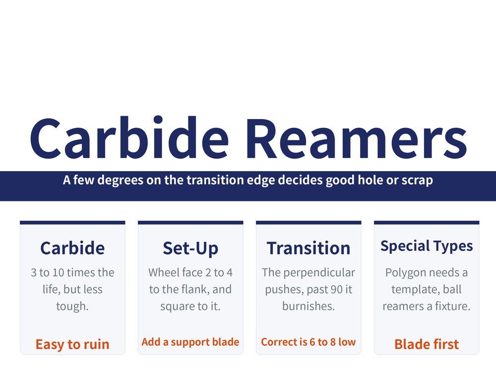
A carbide reamer lasts 3 to 10 times longer than high speed steel, but it is lower in strength and toughness, so it is easier to ruin on the grinder than to improve. This guide covers the tilt angle for carbide reamers, why a small radius must be stoned in afterwards, and the transition edge — the one short edge where a few degrees decides between a good hole and a scrapped part. It closes with three awkward-to-hold special reamers.
1. Carbide reamers: worth grinding, hard to grind
The case for carbide is solid: reaming speed runs several to more than ten times that of a high speed steel reamer, surface finish reaches Ra1.6~0.4μm, accuracy grades 9 to 7, and tool life is 3 to 10 times longer.
The price is that carbide is lower in both strength and toughness than high speed steel, so it is markedly harder to regrind — and the quality of that regrind decides tool life and the hole's finish and accuracy directly. The same tool ground well and ground badly is two different tools. Carbide needs superabrasive wheels: for selection see Diamond or CBN Wheels, and for keeping them true see Truing and Dressing Superabrasive Wheels.
2. The tilt angle β: shrink the contact patch
On the tool grinder, hold a tilt angle β between the reamer axis and the machine centre line so that the wheel face and the reamer flank form a 2°~4° angle. The purpose is the same as on any tool: a small contact patch is what keeps the teeth from burning.
| Item | What to do |
|---|---|
| Wheel attitude | The face stays square to the reamer flank, so the ground clearance does not drift |
| Stability | Add a support blade in front, set a distance H below the reamer centre (same formula family as the flank) |
| When to stop | Stop once the finish reaches Ra0.8~0.2μm and the clearance is on specification |
| Anti-chipping | Do not run it straight off the grinder: stone a small radius where the cutting portion meets the sizing portion |
That last line is the one most often skipped. Carbide has little toughness to spare, and that sharp junction is where chipping starts; a stoned radius lengthens life and improves the machined hole. For the general rake and flank routine, see Regrinding a Reamer.
3. Which line the transition edge sits on
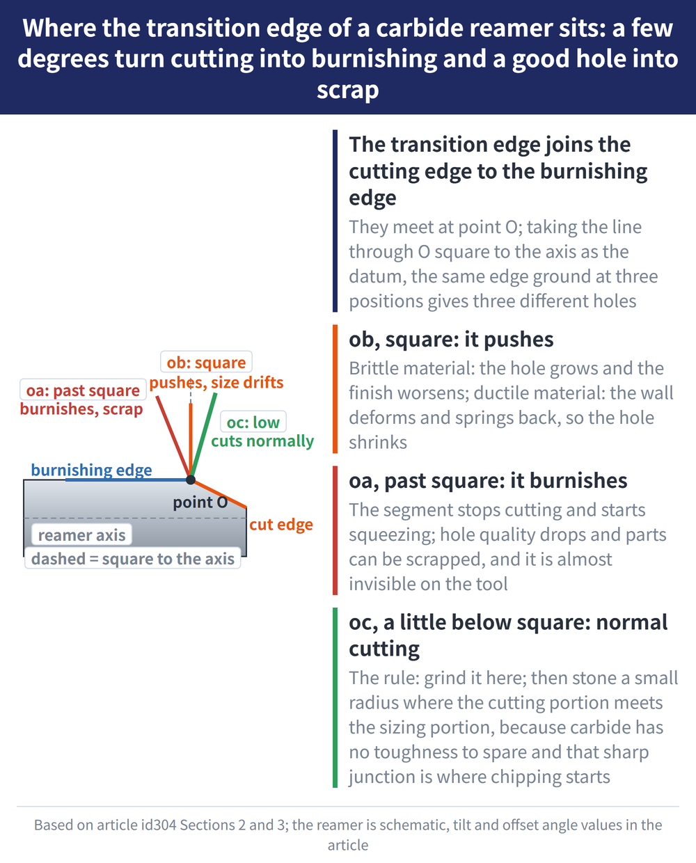
The transition edge is the short segment joining the cutting edge to the burnishing edge, meeting at point O. The angle it is ground at decides hole accuracy and finish outright. Taking the line through O perpendicular to the reamer axis as the datum, the source gives three positions:
| Position | What the edge does | Result |
|---|---|---|
| ob: perpendicular to the axis | Pushes the stock | Brittle material: hole grows, finish worsens. Ductile material: the wall deforms and springs back, so the hole shrinks |
| oa: angle over 90° | Burnishes the stock | Hole quality worse still, and parts can be scrapped |
| oc: angle under 90°, about 6°~8° low | Cuts normally | Every specified figure for the finished hole is met |
The rule: grind the transition edge at oc, meaning 6°~8° down from the perpendicular. Overshoot to the oa side, past 90°, and that segment stops cutting and starts burnishing — the leading cause of poor holes and scrapped parts, and almost invisible on inspection of the tool.
4. Three special reamers, all held awkwardly
| Type | The obstacle | The answer |
|---|---|---|
| Small five-sided polygon reamer | Small diameter, tight tolerance, cannot be held between centres on a tool grinder | Make a five-sided locating template and move to a profile grinder |
| Ball reamer | Inconsistent grind quality, low output | Build a wheel dresser to form the wheel, then improve the grinding fixture |
| Single-blade assembled reamer | Blade and body have to be handled in two stages | Grind the blade first, then grind the whole tool once assembled |
The polygon reamer template follows the tool's own geometry: a V-groove locates the centre and a screw clamps the shank. The template sits on a small magnetic chuck with a back stop at the side, and once indicated in, every feature can be ground, with easy loading and measuring.
5. Ball reamers and assembled reamers
The ball reamer dresser swings a rocker between two 60° centres in a circular path, and an adjusting screw acting through a movable indicator seat brings the diamond spindle to the radius wanted, forming the wheel. The grinding fixture mounts on its own 18° centre hole on a universal tool grinder: for the rake face, free the tooth rest and swing it about 45° clear, using a dish wheel; for the clearance, lock the tooth rest and use a cup wheel.
The assembled reamer goes in two stages. The two clamped faces of the blade are ground first on a tool or surface grinder and lapped to Ra0.1μm before the blade enters the body slot. The body and blade then go on a universal tool grinder together for the diameter, the primary clearance (leaving the land), the transition segment, the burnishing segment and the back taper, again to Ra0.1μm. To regrind a worn blade, slacken the clamp, tighten both radial adjusting screws by the same amount, clamp again and repeat the second stage.
6. Frequently Asked Questions (FAQ)
Q: Why stone a small radius after grinding a carbide reamer?
Because carbide is lower in strength and toughness than high speed steel, and the sharp junction between the cutting and sizing portions is where chipping begins. A stoned radius there extends tool life and improves the machined hole. It is not an optional step.
Q: Can a mis-ground transition edge be spotted from the hole?
The direction shows. Ground on the perpendicular it pushes: brittle material comes out oversize, ductile material springs back undersize. Ground past 90° it burnishes, hole quality drops clearly and parts can be scrapped outright.
Q: Is the 2°~4° figure the angle the wheelhead is swung?
No. It is the angle between the wheel face and the reamer flank, produced by the tilt angle β between the reamer axis and the machine centre line. The wheel face still has to stay square to the flank, or the ground clearance drifts.
Q: Why not assemble the reamer first and grind it in one go?
The two clamped faces of the blade must be ground and lapped to Ra0.1μm first, because they set where the blade sits in the body slot. Grind them only after assembly and the datum itself is out, and no amount of work on the diameter or the edges brings it back.
This article is part of Tool Regrinding: The Complete Guide — Decide Whether to Grind, Then Look Up How, With What, and How to Check; that guide shows how the whole topic fits together.
Published: 2026-08-18|Last updated: 2026-08-18









