
General Machining Practice Rules: What to Do Before, During Setup, During the Cut and After
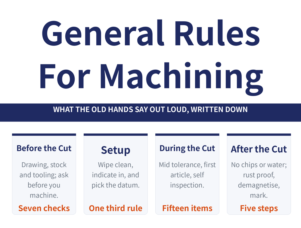
One set of general practice rules that applies to turning, milling, drilling, boring, broaching and grinding alike, listing what to do before the cut, during setup, during machining and after. Most of these are things an experienced hand says out loud but nobody writes down. Here they are as a list you can pin next to the machine, with each rule's status stated plainly.
1. Where these rules come from, and what they count for
The clauses here are compiled from the general machining practice rules in the mainland Chinese industry standard series JB/T 9168.1. Two things need saying up front:
| Question | Answer |
|---|---|
| Is there an equivalent mandatory standard in Taiwan | No. No corresponding mandatory standard is in force, so this article is not a regulatory requirement. Do not cite it as an applicable standard |
| Then why read it | Because the content is general shop discipline - wipe it clean, indicate it in, inspect the first article, remove the burr. None of that changes with the standards system. It works well as a drafting base for your own written procedure |
In short: treat it as a checklist, not as a legal clause. The four sections below are the four stages of the general rules, and they apply to turning, milling, planing, drilling, boring, broaching and grinding alike.
2. Before the cut: seven checks
What these seven have in common is that they all happen before the machine starts, and every one of them guards against the same failure: doing the right thing from the wrong information.
| # | What to do |
|---|---|
| 1 | Check that the drawing, the process sheet and the related technical documents are complete |
| 2 | Read and understand them; if anything is unclear, ask before machining |
| 3 | Verify the stock or semi-finished part against the drawing; report problems and wait until they are resolved |
| 4 | Have all tooling ready; learn the requirements for any new fixture or die first |
| 5-7 | The remaining three cover tools, gauges and machine checks before start, and are the same in nature |
Items 2 and 3 are the two most often skipped and most expensive in the whole set. The first produces a correct part from an incorrect drawing; the second runs every operation on stock that was already wrong. Both are scrap-the-batch mistakes, and both happen before any metal is cut.
3. Setup: two rules for the tool, eight for the part
The tool side is short: wipe the shank, the bar and the bushing clean before mounting, and check the result with a presetter or a trial cut. The eight on the part matter more, and the datum selection rules are the ones worth copying out.
| Item | What the rules say |
|---|---|
| Before clamping | Locating faces, clamping faces, parallels and the matching fixture faces all wiped clean, with no burrs |
| Choosing the locating datum (when the process sheet does not specify) | 1 coincide with the design datum where possible; 2 use one datum for as many faces as possible; 3 for roughing pick an unmachined or low-allowance flat face, usable once only; 4 for finishing the datum should be a machined face |
| With no dedicated fixture | Indicate to the layout lines or the next operation's allowance; indicating accuracy under one third of the size and position tolerance |
| Clamping force | Applied through a support point or face; parts with low rigidity or overhang need auxiliary support |
| Finished faces and soft materials | Use soft packing such as copper shim |
| With clamps | The clamp support should sit slightly above the clamped face, with the bolt as close to the part as possible |
The one third of tolerance rule is one of the few numbers here you can work with directly. For the mechanism behind clamping force and distortion, see why vice clamping distorts the part.
4. Fifteen rules during the cut, and four roughness ceilings
Of the fifteen, four carry numbers and the rest are discipline. The four with numbers can serve directly as handover gates between operations:
| Situation | Ra ceiling |
|---|---|
| Roughing operation with no specified roughness, after machining | Not above 25 μm |
| Before reaming | Not above 12.5 μm |
| Before finish grinding | Not above 6.3 μm |
| Faces due for surface hardening, ultrasonic inspection or burnishing next | Not above 6.3 μm |
Of the discipline items, three cause the most trouble in practice: 1 work toward the middle of the tolerance; 2 when roughing and finishing on the same machine, release the part after roughing, let it cool and re-clamp; 3 batch work requires first article inspection. Two more are safety items: check large parts for movement during machining, and if the sound changes or the surface suddenly worsens, retract and stop. These four Ra values are handover floors; where the drawing is stricter, the drawing wins.
5. Five steps after the cut, plus two on packing up
Post-machining handling is easily treated as housekeeping, but it decides what condition the next operation receives the part in:
| What to do | Why |
|---|---|
| No chips, no water, no dirt; stored tidily | Avoids knocks and scratches, which mostly happen between operations rather than during them |
| Rust-protect anything finished or waiting | The waiting time is often longer than the machining time |
| Demagnetise after magnetic chucking | Residual magnetism attracts swarf and disturbs later measurement and assembly |
| Mark or number matched sets | A mixed-up mating pair is scrap |
| Pass inspection before moving on | Stops a bad part accumulating further machining cost |
Two more on packing up: clean and oil the tooling and return it; keep drawings and process documents clean and never alter them by hand. Rule 9 is also worth singling out: if no separate deburring operation follows, the burr this operation created must be removed in this operation. A burr passed downstream usually never gets removed at all.
6. Two places that point at other standards
The original rules defer twice to other standards, and neither has a Taiwanese equivalent, so both have to be handled locally:
The first is chamfers and fillets: where the drawing and process sheet do not specify their size and tolerance, the rules defer to another standard. With no equivalent in force, the practical answer is to state them explicitly on the drawing, or define the common sizes in your own shop standard, rather than leaving it to whoever is at the machine.
The second is how gauges are used: gauges and micrometers to be pushed or turned in gently and never forced, callipers and dial indicators zeroed beforehand. That is basic measurement discipline and has nothing to do with which standards system you follow. For micrometer use, see the micrometer guide.
7. Frequently asked questions
Q: Do these rules carry legal force in Taiwan?
No. They are compiled from the mainland Chinese industry standard series JB/T 9168.1, and no corresponding mandatory standard is in force in Taiwan, so this article is not a regulatory requirement. The practical use is as a drafting base for your own written procedure: the clauses themselves are general shop discipline, and wiping clean, indicating in, first article inspection and deburring do not change with the standards system. To claim compliance externally, cite your own procedure, not this article.
Q: How do I pick a locating datum when the process sheet does not specify one?
The rules give four principles in a meaningful order. Make the locating datum coincide with the design datum where you can, and use one datum for as many machined faces as possible. For roughing, choose an unmachined or low-allowance flat face, and use it once only. For finishing, the datum should be a machined face. With no dedicated fixture, indicate to the layout lines or the next operation's allowance, keeping indicating accuracy under one third of the size and position tolerance.
Q: Why release and re-clamp the part between roughing and finishing?
Because the heat and the clamping stress from roughing are still in the part. Going straight into finishing measures a thermally expanded part, and the size shifts again as it cools; the elastic deformation from clamping also springs back on release. The rules say this "should generally" be done when roughing and finishing share a machine. Whether you actually do it depends on part rigidity, how much was removed and how tight the tolerance is.
Q: Can the four roughness ceilings be used as acceptance criteria?
They work as handover gates between operations, as long as you read them as ceilings rather than targets. A roughing operation with no specified roughness should come out at Ra no worse than 25um; before reaming, 12.5um; before finish grinding, 6.3um; and faces due for surface hardening, ultrasonic inspection or burnishing, also 6.3um. The meaning is "do not pass it downstream if it is worse than this". Where the drawing asks for more, the drawing governs.
This article is part of Manufacturing Process: The Complete Guide - Set the Datum First, Then Sequence, Allowance and Dry Cutting; that guide shows how the whole topic fits together.
Published: 2026-08-30|Last updated: 2026-08-30









