
High Speed Grinding Wheels and Parameters: Five Selection Items, the k Value Chart and a Parameter Table
A high speed wheel is not an ordinary wheel spun faster. Abrasive, grit, grade, structure and bond each move in a different direction, and the bore to diameter ratio tightens as speed rises. This article puts the five selection items, the k value chart and a parameter table for cylindrical grinding of steel in one place, with the applicable conditions on every figure.
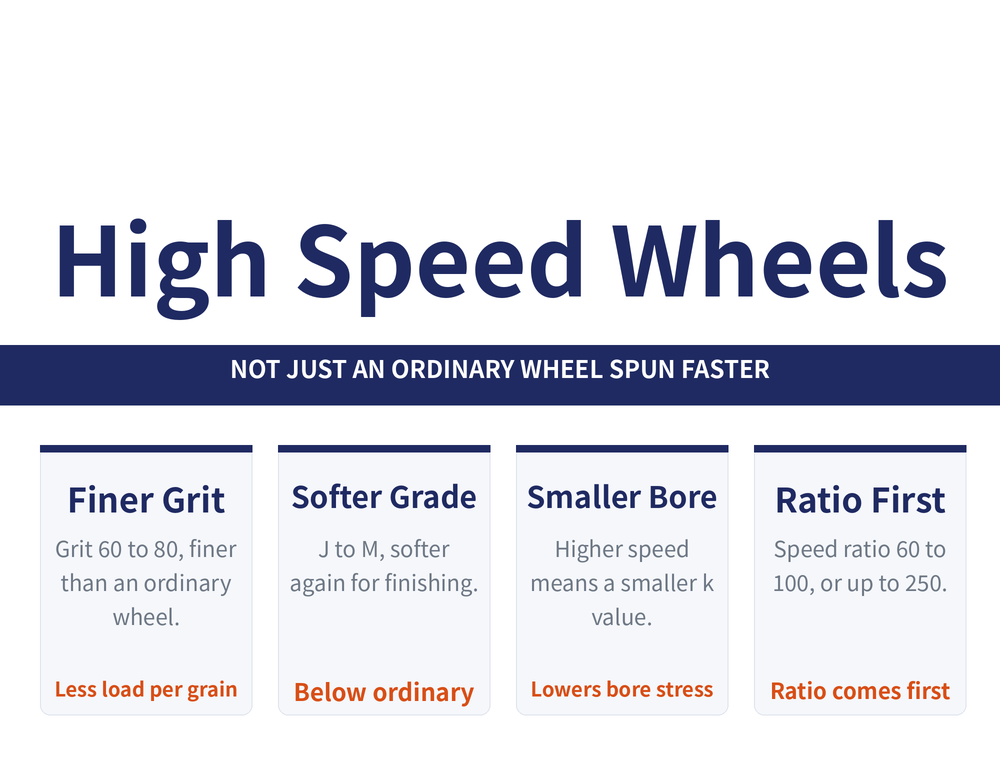
1. Five selection items, each moving a different way
A high speed wheel differs from an ordinary one not by being a higher grade but by five specifications each moving in its own direction:
| Item | How to choose |
|---|---|
| Abrasive | A tougher alumina, most commonly brown alumina (A), for carbon and alloy steel; for ductile iron, brown alumina or a blend with green silicon carbide (GC) |
| Grit | Finer than an ordinary wheel, commonly 60, 70 or 80. Less load per grain, slower dulling, more even self-sharpening and better form holding |
| Grade | Slightly softer than ordinary, generally J to M. The grade must be uniform, or uneven grain release destroys wheel form and running smoothness |
| Structure | The face needs some fine porosity to clear swarf and heat, but not large pores, which worsen uneven grain release |
| Bond | Usually a boron glass ceramic bond, a vitrified bond with boron, lithium, barium and calcium added for strength |
Three refinements apply to grit and grade: 1 finishing generally calls for 70 or 80; 2 ductile materials, or work where burn must be avoided, call for a slightly coarser grit; 3 above 80 m/s the grit should be 80 to 100. On grade: softer for finishing, harder for roughing and large stock removal, and softer again for unbalanced parts such as crankshafts and camshafts, where work speed cannot be raised to control burn. For reading wheel markings see the grinding wheel marking guide.
2. Bore to diameter ratio k tightens with speed
A wheel with a bore should have the smallest practical bore to diameter ratio k = rf / R, which lowers stress at the bore wall and guards against bursting. The allowable ceiling on k tightens as speed rises:
| Wheel speed m/s | below 45 | 45 to 60 | 60 to 80 | 80 to 100 |
|---|---|---|---|---|
| Maximum k | 0.6 | 0.5 | 0.33 | 0.2 |
From 0.6 down to 0.2 is a wide swing, and this column is often the real reason a wheel cannot simply be moved up a speed class: same outside diameter, different bore, different permissible speed. For reinforcement of the bore area itself see section 4 of three things to settle before high speed grinding. One more point on dressing: the dresser contact point should sit at the same position as the grinding point on the workpiece, which limits the effect of any imbalance.
3. Speed ratio comes first
The first parameter to fix in high speed grinding is not the feed but the ratio of wheel speed to work speed. Wheel speeds of 50 to 60 m/s are usual, reaching 80 m/s where conditions allow.
| Case | Speed ratio (wheel to work) |
|---|---|
| General | 60 to 100 |
| Slender shafts and unbalanced parts | Lower work speed, ratio 100 to 250 |
Why work speed matters: high speed grinding raises temperature and burn becomes easy, and raising work speed shortens the time the heat source acts on any one point and lowers the feed per revolution, which improves burn markedly. Too high, though, and the work and wheel system goes into self-excited chatter while centre wear accelerates, so there is a ceiling.
4. Axial feed and depth of cut
Both act on the process the same way: increase them and output rises, but grinding force rises too, wheel wear becomes uneven and the roughness value climbs. Depth of cut also has to respect the rigidity of machine and part, and whether the wheel motor has the power.
| Item | Usual value |
|---|---|
| Axial feed fa | (0.2 to 0.5) bs / r, where bs is wheel width |
| Depth of cut fr, roughing | 0.02 to 0.07 mm/dst |
| Depth of cut fr, finishing | 0.005 to 0.02 mm/dst |
Direction of choice: take the higher values on short stiff parts and the lower values on slender shafts. ⚠ The unit dst is not a standard unit and has no accepted definition; this site reproduces it without inventing one. When quoting these values, keep the original unit; do not convert it to something else until the definition of dst is confirmed.
5. Parameter table for cylindrical grinding of steel
This table ties the previous sections together, with one set of values per speed band:
| Wheel speed m/s | Speed ratio | Plunge mm/min | Traverse speed m/s | Depth mm/dst |
|---|---|---|---|---|
| 45 | 60 to 90 | 1 to 2 | 0.016 to 0.033 | 0.015 to 0.020 |
| 50 to 60 | 60 to 90 | 2 to 2.5 | 0.033 to 0.042 | 0.020 to 0.030 |
| 80 | 60 to 100 | 2.5 to 3 | 0.042 to 0.050 | 0.040 to 0.050 |
⚠ The scope is in the title: high speed cylindrical grinding, steel parts. Change the process to surface or internal grinding, or change the material, and the table is out of range. Do not extrapolate. For general machining formulas see the machining formula cheat sheet.
6. Frequently asked questions
Q: Why does a high speed wheel use a finer grit and a softer grade?
Because at higher speed more grains are engaged per unit time, so the load on each one falls. A finer grit spreads that load further, dulls more slowly and self-sharpens more evenly, which holds the wheel form. A slightly softer grade extends the same logic: it lets a dulled grain release when it should. Grit is commonly 60 to 80 and grade J to M, with grit going to 80 to 100 above 80 m/s.
Q: Two wheels of the same diameter, different maximum speeds. Why?
Very likely the bore to diameter ratio k. The higher the speed, the smaller k has to be: up to 0.6 below 45 m/s, 0.5 from 45 to 60, 0.33 from 60 to 80, and only 0.2 from 80 to 100. A relatively smaller bore means lower stress at the bore wall, and the bore wall is where a burst normally starts. So the same outside diameter with a different bore genuinely carries a different permissible speed; the marking is not being conservative for its own sake.
Q: Is a higher work speed always better against burn?
The direction is right but there is a ceiling. Raising work speed does shorten the time the heat source acts on any one point and lowers the feed per revolution, which improves burn noticeably. Too high, though, and the work and wheel system falls into self-excited chatter and centre wear accelerates. In practice the control is the speed ratio: 60 to 100 in general, and 100 to 250 for slender shafts and unbalanced parts, where the work speed has to stay lower.
Q: What unit is the dst in mm/dst?
dst is not a standard unit and no accepted definition exists, so this site reproduces it without translating it into something else. The practical handling is to carry the unit with the number: when quoting values such as 0.02 to 0.07, go back to the original document, confirm what dst means there, and convert only after that. Do not assume it means per stroke or per revolution. A figure that is clear while its unit is unresolved is easier to misuse than it looks.
This article is part of Grinding Wheels and Machines: The Complete Guide - Reading the Wheel, Mounting It, Dressing It, and Tracing Defects; that guide shows how the whole topic fits together.
Published: 2026-08-30|Last updated: 2026-08-30









