
Peck Rhythm for Deep-Hole Drilling on a Lathe: How Hole Depth Stage and Material Set the Retract Interval
Drilling a deep hole on an engine lathe with a standard twist drill on an extension bar leaves you no canned cycle to call — the operator decides when to retract. This guide covers exactly that decision: within one hole, drilling solid material and enlarging an existing hole call for different retract intervals; the smaller the hole, the shorter the interval has to be; and there is one feed re-engagement rule that is easier to miss than the retract itself. All three sets of measured intervals here are tied to their own hole diameter and length-to-diameter ratio, and each is flagged as not transferable.
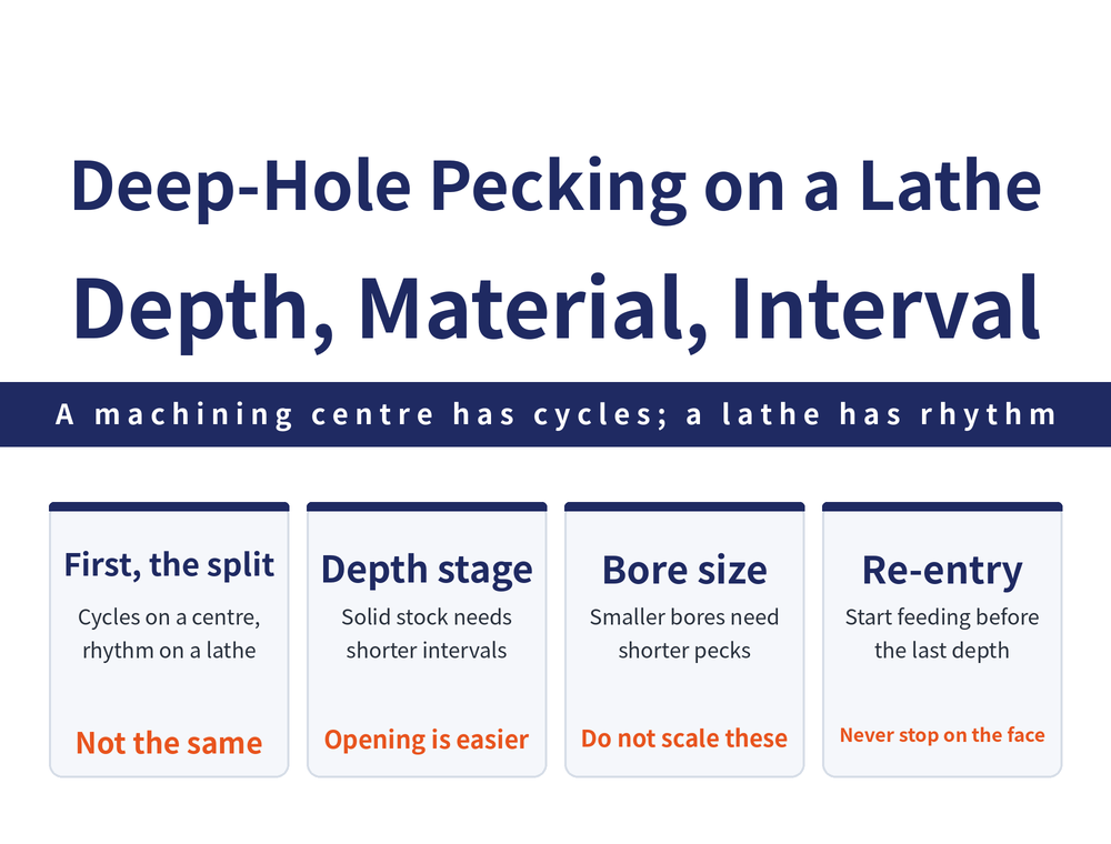
A deep hole gets finished, and the drill survives, because the chips are getting out — not because of the speed or the feed. On a lathe the only way to get them out is to pull the drill back. How often you retract, and when, decides whether the hole runs through or the drill snaps off inside it.
1. First, the scope: this is not the canned peck cycle on a machining centre
The word peck covers two very different situations. On a machining centre, pecking is a canned-cycle matter — pick the partial-retract or full-retract method, enter the peck depth as a parameter, and the machine runs it. For that, see Peck Drilling: When You Need Interrupted Feed and How to Set It.
This article is about the other case: on an engine lathe, drilling deep with a standard twist drill on an extension bar, how the retract interval itself should shift with the hole depth stage and the material. There is no cycle to load here; the carriage is fed by hand and the interval is judged one pass at a time. So this guide does not repeat cycle commands or general cycle rules — it covers the shop-floor rhythm only.
2. Why you drill a pilot hole first, then switch to the extension bar
The first stretch of a deep hole cannot be cut with a long bar. The standard sequence is to drill the pilot hole as deep as a standard-length drill will reach, then switch to a drill mounted on an extension bar and carry on from there.
The reason is straightforward: an extension bar is long and slender and short on rigidity. Without a length of finished bore wall to steady it, the point wanders, vibration sets in, and once the hole axis leans everything after it is off. The pilot hole is that handrail. For how the whole pass sequence is laid out, see How to Plan a Turning Feed Path.
3. Three sets of measured intervals, each locked to its own diameter and ratio
The table below gives retract intervals from three real cases. Read each row whole; do not lift the middle number on its own — every interval is tied to one specific diameter and ratio.
| Case and material | Diameter and ratio | Stage | Measured retract interval | Stated limit |
|---|---|---|---|---|
| Alloy steel grinder spindle oil hole | φ6 mm, 720 mm long, ratio 120 | Solid material, extension bar | Retract to clear chips every 5–6 mm | Measured at φ6 mm, ratio 120; must not be scaled to any other diameter |
| Austenitic stainless steel shaft | φ32 mm, depth ratio 38.2 | Solid material, extension bar | Retract to clear chips every 20–25 mm | Measured at φ32 mm, depth ratio 38.2; must not be scaled to any other diameter |
| Austenitic stainless steel shaft | φ42 mm enlarging, same hole | Enlarging, less stock | May be relaxed to every 40–50 mm | Measured for φ42 mm opening out a φ32 hole; must not be scaled to any other diameter |
| Pure copper small-bore nozzle | φ0.5 mm, ratio 10 | Small-diameter drilling | Retract after roughly 0.5 mm of depth | Measured at φ0.5 mm, ratio 10; must not be scaled to any other diameter |
Those four intervals span a hundredfold range, from 0.5 mm to 50 mm, and can be neither interpolated nor extrapolated — the source forbids scaling them. The table shows what the interval moves with, not how many millimetres your own hole needs.
4. Within one hole, solid drilling and enlarging have different rhythms
Rows two and three above are two stages of the same hole and are worth reading together. At φ32 mm through solid material the drill has to come out every 20–25 mm; switching to a φ42 mm drill to open out that same hole allows 40–50 mm.
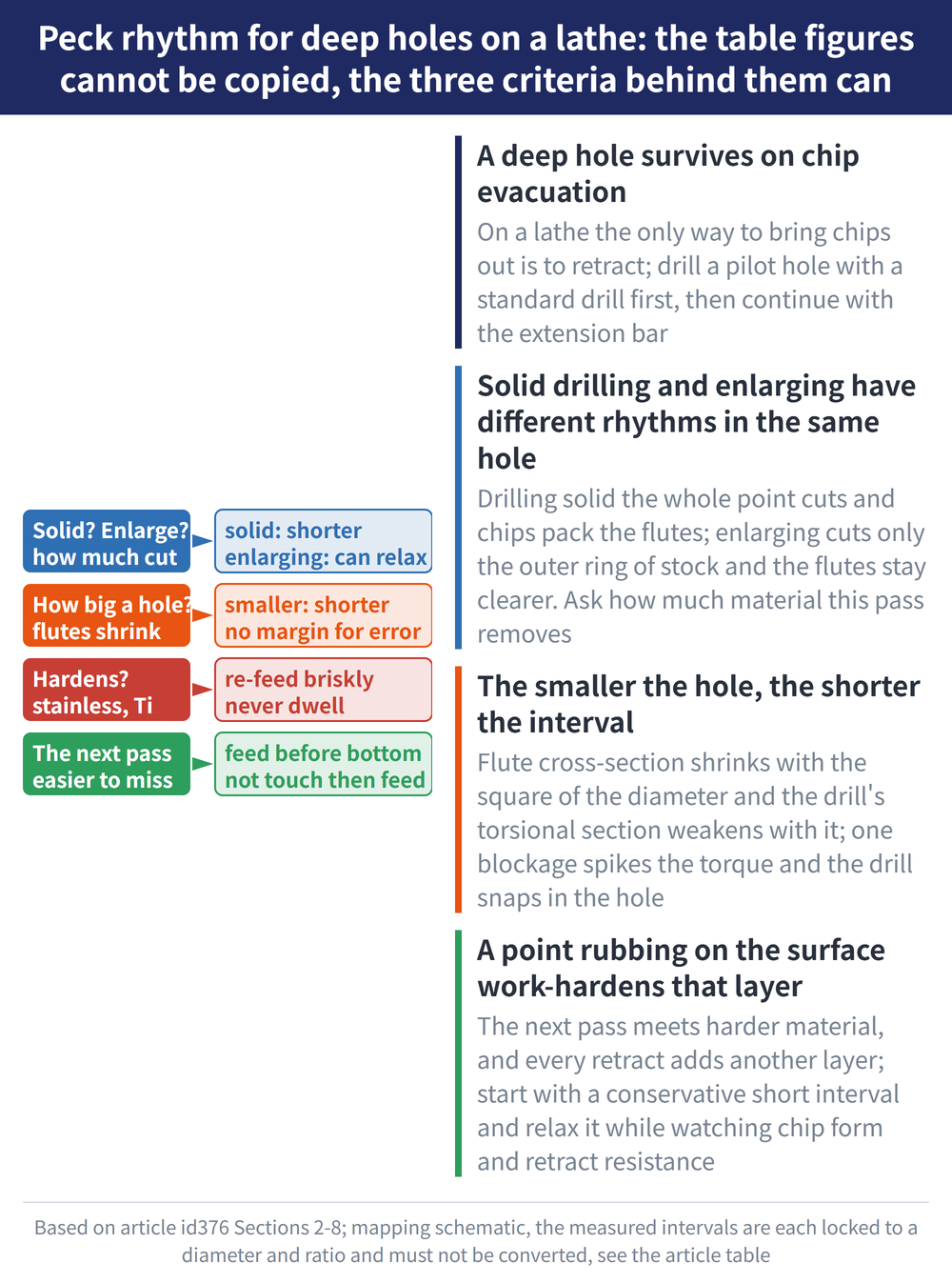
The difference is how much material is being removed. Drilling solid puts the whole point in cut and packs the flutes with chips; enlarging cuts only the ring of stock left around the edge, so there is less of it and the flute is comparatively clear. The less stock a pass removes, the longer the retract interval can be.
So do not treat hole depth as the only variable when judging when to pull out. The question is how much material this pass is cutting — change the stage within one hole and the answer changes. Both intervals are measured values for the specific diameter pairing named above and must not be scaled to any other diameter.
5. The smaller the hole, the shorter the interval
On the pure copper nozzle, the φ0.5 mm hole has to be retracted after roughly 0.5 mm of depth — about one diameter per peck. The φ3 mm hole on the same part also needs repeated retracts to clear chips, or the drill will break.
The flute cross-section shrinks with the square of the diameter while the drill's own torsional section weakens in step. A small hole has no margin for error: one packed flute spikes the torque and the drill snaps off inside. Work sensitively here and do not rush the pass.
That 0.5 mm figure is a measured value for a φ0.5 mm pure copper hole at ratio 10 and must not be scaled to any other diameter. What does transfer is the direction: the smaller the hole, the shorter the peck interval has to be.
6. Easier to miss than the retract: start the next pass early
Once the chips are cleared, the drill has to go back in. There is a rule at this point, and missing it undoes every bit of rhythm control described above.
When you move the carriage in for the next pass, engage the feed roughly 1 mm before the depth reached by the previous pass. Never let the drill touch the surface to be cut and only then start feeding.
In other words, the feed must already be running by the time the drill reaches the bottom of the hole; it must not start moving on contact. In the φ6 mm alloy steel case the automatic feed was 0.05–0.08 mm/r — again a measured value at that diameter and ratio, not to be scaled. To work out your own feed, see Turning Calculation Formulas.
The same applies on the way out: stop the feed and retract decisively, without dragging it out. For retract distance and method, see Lead-In and Overtravel Length.
7. Why that rule matters most on work-hardening materials
A drill point resting on the surface to be cut is not doing nothing. The cutting edge rubs and burnishes in place, and that layer of surface work hardens. What the next pass has to cut is then harder than the original material.
Two consequences follow: further drilling becomes difficult, and drill wear speeds up. It also accumulates — every retract adds another hardened layer, so the deeper stretches get progressively harder to enter.
This matters most on work-hardening-sensitive materials such as austenitic stainless steel and titanium alloys. The hole in rows two and three above is austenitic stainless steel, and holding its interval to 20–25 mm is not only about chip evacuation — it also keeps every pass cutting cleanly instead of dwelling on the surface.
8. How to set the interval for your own hole
The numbers in the table cannot be copied, but the logic behind them can. Three transferable questions:
| Question to ask | Which way to move |
|---|---|
| Is this pass cutting solid material, or enlarging an existing hole? | Shorten for solid material; a longer interval is allowed when enlarging |
| How large is the hole? | The smaller the diameter, the shorter the interval |
| Does the material work harden? | If so, retract and re-engage decisively; no dwelling allowed |
In practice: start from a conservatively short interval, then relax it gradually while watching the chip form and the resistance on retract. Whether the chips come out broken, curled or balled up tells you more about how evacuation is going than any table can. Prove the first hole out on a sample piece rather than running straight to the limit.
For the full reading guide on this topic, see Turning Toolpaths: The Complete Guide.
9. Frequently Asked Questions (FAQ)
Q: Is pecking on a lathe the same thing as a peck cycle on a machining centre?
No. On a machining centre the peck depth is entered as a cycle parameter and the machine executes partial or full retract. On a lathe drilling deep with a standard twist drill on an extension bar there is no cycle to load; the carriage is fed by the operator and the retract interval is judged on the spot from the depth stage and the material.
Q: Can I apply the 5–6 mm or 20–25 mm intervals to my own hole?
No. Each figure is locked to a specific diameter and ratio: 5–6 mm is φ6 mm at ratio 120; 20–25 mm and 40–50 mm are φ32/φ42 mm at depth ratio 38.2; 0.5 mm is φ0.5 mm at ratio 10. The source forbids extrapolation, so prove your own hole out on a sample.
Q: Why can the enlarging stage retract less often than solid drilling?
Because enlarging cuts only the ring of stock at the edge, so there is less material and the flute stays comparatively clear, whereas drilling solid puts the whole point in cut and packs the flutes quickly. The less stock a pass removes, the longer the retract interval can be.
Q: Why should the next pass engage feed about 1 mm early?
To stop the drill point rubbing while parked on the surface to be cut. Dwelling work hardens that layer, so the next pass meets harder material, which makes further drilling difficult and accelerates drill wear. It matters especially on work-hardening-sensitive materials such as austenitic stainless steel and titanium alloys.









