
How to Sequence Thin-Wall Turning: Roughing, Semi-Finishing, Finishing and Four Countermeasures Against Distortion
A thin-walled part cannot be run with roughing and finishing alone. Two operations are enough for a rigid shaft, but a thin-walled part needs at least three — rough turning, semi-finish turning, finish turning — with the semi-finishing pass there specifically to correct the distortion roughing has already caused, and more operations added if measurement says so. This guide covers how the three operations divide the work, why inside and outside surfaces are alternated stage by stage, what each of the four distortion countermeasures (clamping, heat, order, residual stress) addresses, and the trade-offs among six workholding methods.
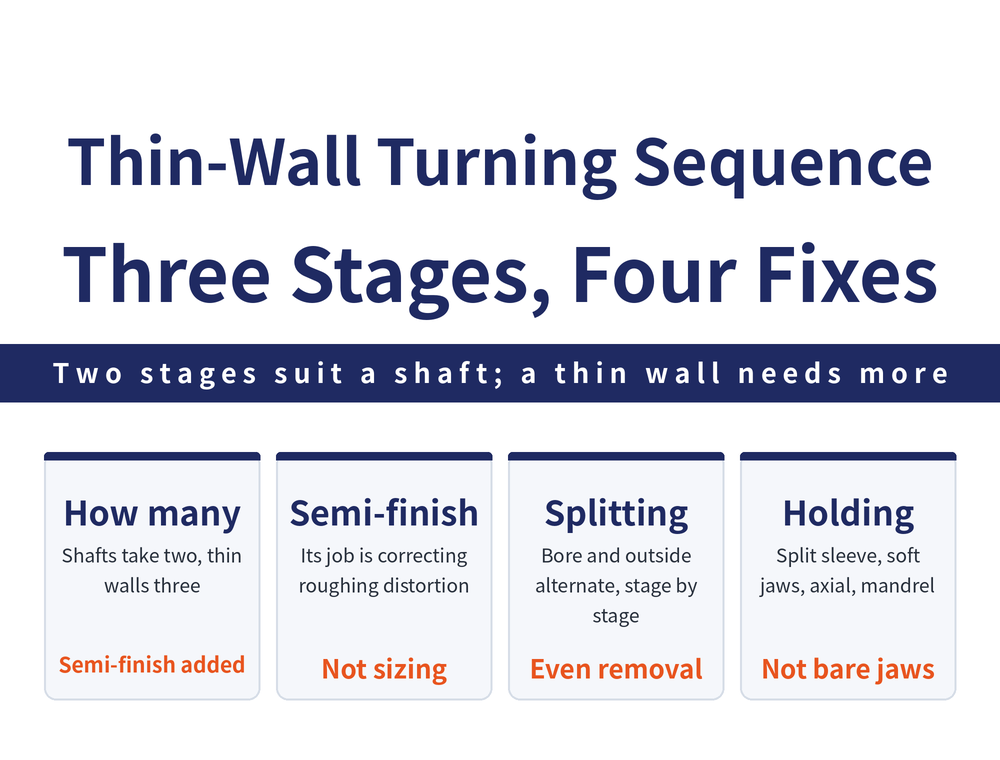
This article is about thin-walled parts only. For the general division of machining stages, operation concentration versus dispersion, and the ordering principles that apply to ordinary parts, see How to Plan a Machining Sequence; none of that is repeated here. Thin-walled parts need their own article because they push the operation count from two up to three or more — not for the sake of a tidier process sheet, but because roughing will distort the part, and without an operation dedicated to correcting that, finishing simply reproduces the distortion.
1. Two Operations Suffice for a Shaft, Three at Minimum for a Thin Wall
A shaft-type part with good structural rigidity distorts little when stock is removed, so it is normally given just two operations: rough turning and finish turning.
Thin-walled parts are different. They need at least rough turning, semi-finish turning and finish turning — three operations, sometimes more. The job of the semi-finishing pass is specific: to correct the distortion caused by roughing. If that still does not remove it, further cutting operations are added according to actual measured values.
The factors behind thin-wall distortion are complex (material, structural shape, cutting force, cutting heat and so on) and hard to predict in advance, so the number of operations and the stock left for each can only be set from measurement, not filled in from a table.
2. What Each of the Three Operations Does
| Operation | Main task | Key point in sequencing |
|---|---|---|
| Rough turning | Remove most of the stock | Take the largest stock areas first |
| Semi-finish turning | Correct distortion from roughing | Kept separate, not run straight on |
| Finish turning | Cut to final size and surface quality | Entered only after distortion is corrected |
Three operations is not the same as three passes of the tool. One operation may contain several passes, while between operations the part can be left to cool naturally or moved to a different workholding method — which is exactly why thin-walled parts keep them apart.
3. Alternate Inside and Outside Surfaces Instead of Finishing One Side Outright
Thin-walled parts should be staged by roughing and finishing: inside and outside surfaces are each rough machined first, then semi-finish machined, and so on, removing the excess evenly step by step.
Doing the opposite — turning the outside diameter straight to final size and only then boring the inside — leaves the finished surface to carry all the later cutting and clamping forces on its own. However accurately it was cut, it will be pushed out of shape.
State the cost up front: this approach lengthens the tool path and lowers machining efficiency. What it buys is accuracy. On a large batch, that trade has to be worked out case by case.
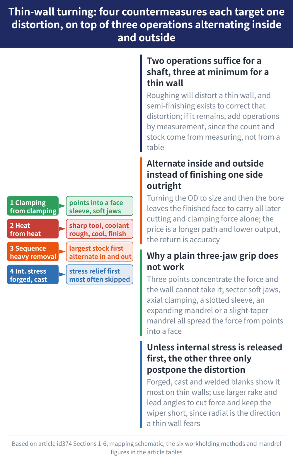
4. Four Countermeasures Against Distortion
| Countermeasure | What to do | Distortion addressed |
|---|---|---|
| 1. Clamping | Enlarge the contact area so clamping force spreads evenly; use a split sleeve or special soft jaws | Distortion from clamping force |
| 2. Heat | Keep the tool sharp and apply cutting fluid; separate roughing from finishing and let the part cool naturally | Thermal distortion from cutting heat |
| 3. Order | When roughing, take the areas carrying the most stock first | Distortion where heavy stock is removed |
| 4. Residual stress | Apply suitable heat treatment before and after roughing to relieve residual stress | Residual stress left by forging, casting or welding |
The one most often skipped is the fourth. Residual stress in forgings, castings and weldments shows up especially clearly on a thin wall; leave it in place and the first three countermeasures, however carefully applied, only postpone the distortion.
5. Workholding: Why a Plain Three-Jaw Grip Does Not Work
A plain three-jaw chuck grips at three points, so the clamping force is concentrated and a thin wall cannot take it. These six methods are the usual replacements:
| Workholding method | Suits | Characteristics |
|---|---|---|
| Single-setup turning | Short, small thin-walled parts | Holds bore-to-OD concentricity; cool after roughing, then finish |
| Sector soft jaws | Parts needing a radial grip | Larger contact area; jaw arc diameter equals the clamped datum diameter |
| Axial clamping fixture | Parts with a face to press on | Radial location plus axial pressure on the face; cuts distortion sharply |
| Split sleeve | Tight concentricity and bore roundness | Large contact area, clamping force evenly distributed |
| Expanding mandrel | Finishing the OD off the bore and large face | Grips by elastic deformation at the slit; quick to load and unload |
| Small-taper mandrel | Machining the OD located off the bore | Accurate; no axial location, low force capacity, awkward to load |
An expanding mandrel has a few common construction values: a plug taper angle of about 30°, a thinnest wall of 3–6 mm, and three equally spaced slots in the expanding sleeve so the expanding force is uniform. The shared logic is one line — spread the clamping force from a few points into a face. For the general case of a workpiece distorted by clamping, see Vise Clamping and Workpiece Distortion.
6. Matching the Tool and the Cutting Data
On the tool: use a larger rake angle and a larger lead angle to bring cutting force down, keep tool holder rigidity high, and do not let the wiper edge run long (0.2–0.3 mm). An over-long wiper edge raises the radial force component, and radial is precisely the direction a thin wall fears most.
On cutting data: when the machine tool has low rigidity or poor accuracy, cutting speed should be reduced accordingly. Radial cutting force readily sets off vibration and distortion, and that is the biggest difference between a thin-walled part and an ordinary one when picking parameters.
For the basic cutting speed and spindle speed conversions, see Turning Machining Formulas.
7. How the Stock Is Split, and Why Measurement Decides
Three operations is the starting point, not the end of it. Measure once after semi-finishing; if distortion is still there, add another cutting operation. This step cannot be shortcut into a rule of thumb, because material, wall thickness and blank-making process all change the result.
How much to leave for each operation, and whether roughing should be split into two passes, is a question of depth of cut and finishing allowance — see Turning Depth of Cut and Finishing Allowance.
The operation counts, staging principles and workholding methods here are compiled from general turning process references. There is no universal figure for how much a thin-walled part will distort, so always work from your own blanks and your own measurements.
For the full reading guide on this topic, see Turning Toolpaths: The Complete Guide.
8. Frequently Asked Questions (FAQ)
Q: Does a thin-walled part always need three operations?
A thin-walled part needs at least rough turning, semi-finish turning and finish turning, sometimes more; it is the rigid shaft-type part that gets by with roughing and finishing only. Three is a floor, not a ceiling — if distortion remains after semi-finishing, add further cutting operations according to actual measured values.
Q: Can semi-finishing be dropped by leaving more stock at roughing?
No. Semi-finishing exists to correct the distortion roughing has already caused, not simply to take another layer off. However much stock roughing leaves, that distortion is still in the part, and finishing will only reproduce it.
Q: Why is a plain three-jaw chuck not recommended for thin-walled parts?
Because the clamping force is concentrated on a few contact points, and a thin wall distorts under it, which costs both dimensional and form accuracy. The countermeasure is to enlarge the clamping contact area so the force spreads evenly, usually by switching to a split sleeve or special soft jaws.
Q: Can thin-wall distortion be calculated in advance?
Hardly. The factors are complex — material, structural shape, cutting force and cutting heat all play a part — and they are difficult to estimate beforehand. The practical approach is to set the best operation sequence and per-operation stock from actual measurement rather than from a calculated figure.









