
Ten Tool Wear Types: From Five Root Loads to the Right Fix
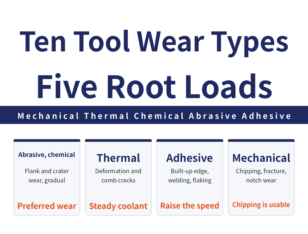
A tool does not fail in one way — it fails in ten. Reading the marks left on the edge tells you whether to slow down or speed up, change grade or fix the clamping. This guide groups the ten wear patterns under five root loads, so you can identify what you are looking at and act on it.
1. Five Root Loads Behind Every Wear Pattern
Ten patterns sound like a lot, but almost every one traces back to one of five load types — or a combination of them. Knowing the root matters more than memorising names, because the fix follows the root.
| Load type | What happens at the edge |
|---|---|
| Mechanical | Pressure on the cutting edge causes breakage |
| Thermal | Temperature swings cause cracks; heat causes deformation |
| Chemical | Carbide reacts with the workpiece material |
| Abrasive | Hard inclusions in the material grind the edge away |
| Adhesive | Sticky material builds up or welds onto the tool face |
How much of each load a grade can take is a material question — see Selecting Tool Material and Coating by Workpiece.
2. Abrasive and Chemical: Two Wear Types That Play by the Rules
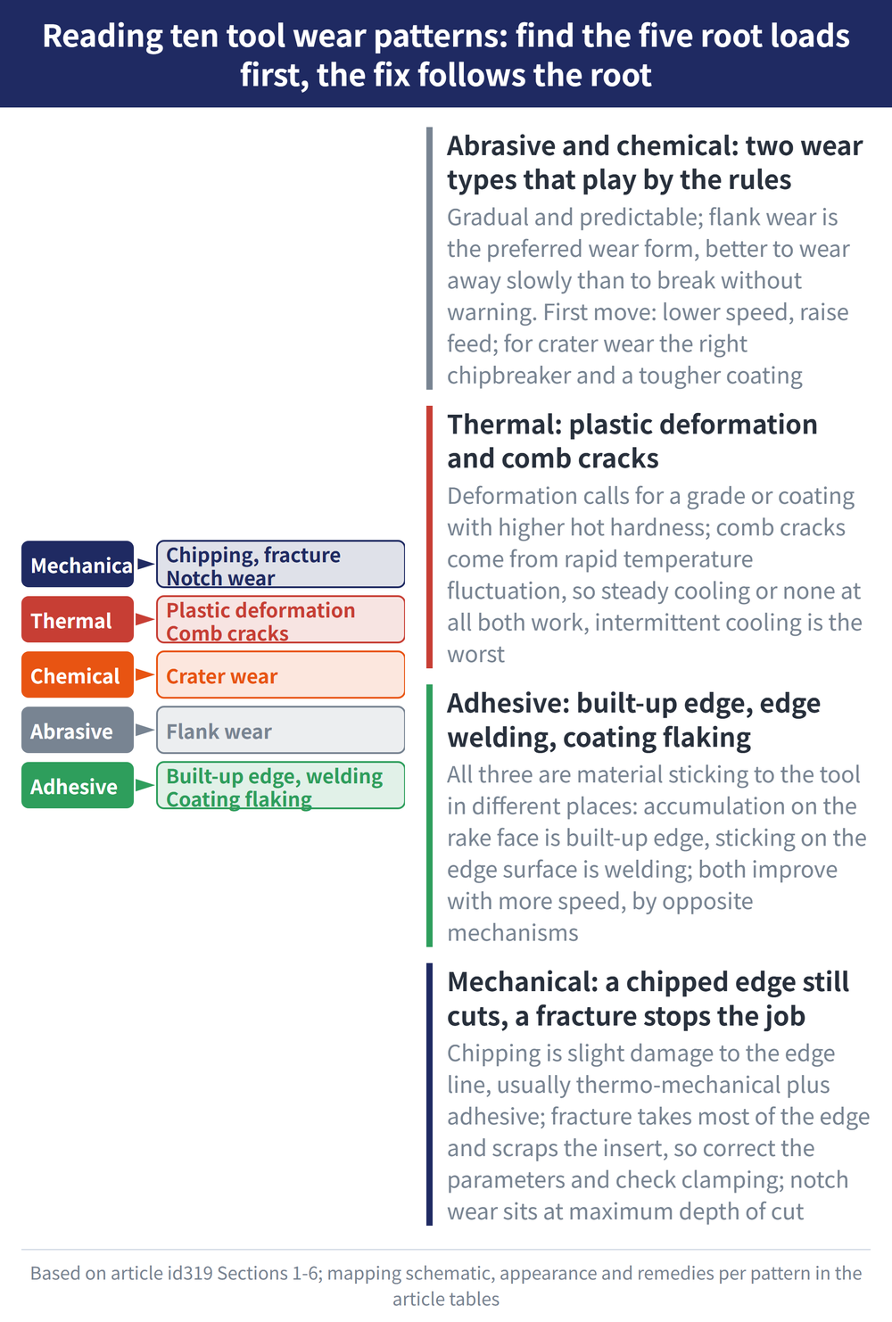
Both develop gradually and predictably, which makes them the easier pair to manage. The source calls flank wear the preferred wear form — meaning it is better to let a tool wear away this way than to have it break without warning.
| Pattern | What it looks like | First move |
|---|---|---|
| Flank wear (abrasive) | Starts at the edge line and works downwards | Lower cutting speed and raise feed at the same time |
| Crater wear (chemical) | Chips rub a hollow into the rake face | Lower speed, choose the right chipbreaker and a tougher coating |
Three further options for crater wear: reduce feed to lower the stress on the tool, move to a coated grade that protects the rake face, or change the tool geometry to reduce the force acting directly on it. For coating choices see Common Tool Coating Materials.
3. Thermal: Plastic Deformation and Comb Cracks
Plastic deformation is a permanent change in the shape of the cutting edge — either inward (the edge is depressed) or downward (the edge collapses). It happens when the edge is stressed beyond the yield strength and temperature limit of the tool material.
The two main fixes are a grade with higher hot hardness, or a coating that improves resistance to deformation. A supplementary source adds: lower the cutting speed to reduce heat, lower the feed to reduce pressure, reduce the edge hone or optimise the edge geometry, and consider aluminium titanium nitride or aluminium oxide coatings to insulate against cutting heat.
Why both flooding with coolant and using none at all can work for comb cracks. The root cause is rapid temperature fluctuation, not high temperature as such. So either cool steadily and continuously, or do not cool at all and let the temperature stay stable — the worst option is intermittent cooling.
Comb cracks are narrow fissures running roughly perpendicular to the edge line, which is where the comb-like appearance comes from. Some stay in the coating, others extend down into the substrate. Beyond the coolant strategy you can move to a tougher grade, or choose a PVD coating — it puts the tool surface under compressive stress, which effectively stops cracks from forming.
4. Adhesive: Built-Up Edge, Edge Welding and Coating Flaking
All three involve material sticking to the tool, but the location and the mechanism differ, and so does the fix.
| Pattern | Where it sticks | First move |
|---|---|---|
| Built-up edge (BUE) | Material accumulates on the rake face | Raise cutting speed; use a sharper edge on soft, sticky material |
| Edge welding | Softened chips weld onto the edge surface | Increase coolant flow, or raise speed so chips do not chill abruptly |
| Coating flaking | Coating separates and exposes the layer beneath | Raise cutting speed and move to a thinner coating |
The dangerous moment with built-up edge is when it breaks away — it often takes the coating, and sometimes part of the substrate, with it. Both BUE and edge welding respond to higher speed, but for opposite reasons: the first reduces the chance of material sticking to the rake face, the second keeps chips hot so they do not chill and become tacky. Judge by location — material piled on the rake face is BUE, material stuck to the edge surface is welding.
5. Mechanical: Chipping, Fracture and Notch Wear
| Pattern | What it looks like | First move |
|---|---|---|
| Chipping | Slight damage to the edge line, usually thermo-mechanical plus adhesive | Identify which wear state caused it, then treat that cause |
| Fracture | Most of the cutting edge breaks away; the insert is scrap | Correct the cutting parameters and check clamping stability |
| Notch wear | Excessive local damage at maximum depth of cut | On work-hardening material, use a smaller entering angle or change the depth |
Four further options for chipping: a grade with better mechanical shock resistance, a larger lead angle to thin the chip, better rigidity in the machining system, and a larger edge hone for edge strength. For notch wear, first establish whether chemical wear dominates — it develops regularly, while adhesive and thermal wear grow irregularly, and work hardening and burr formation are major contributors to the latter. On edge preparation see How Edge Honing Affects Coating Adhesion.
6. Chipping or Fracture: One Word Apart, One Tool Apart
These two are the easiest to confuse and the consequences are very different. Many operators change the tool the moment they see damage at the edge — but a chipped edge is still usable. What must stop the job is a fracture.
| Comparison | Chipping | Fracture |
|---|---|---|
| Extent of damage | Slight damage to the edge line | Most of the cutting edge breaks away |
| Still usable? | Yes, but watch it | No, the insert is scrap |
| Main cause | Thermo-mechanical and adhesive combined | Load beyond capacity, often the end point of runaway wear |
Telling these apart avoids both wasting tools and running past the point where one should have been changed. On when regrinding is worth it, see Is Regrinding and Recoating Worth It.
7. Frequently Asked Questions (FAQ)
Q: Why is flank wear considered a good thing?
Because it develops regularly and predictably, so tool change intervals can be planned. Sudden chipping or fracture is the real problem.
Q: There is a small notch in the edge — must I change the tool?
A chipped edge can still be used, though it should be watched. What must stop the job is fracture, where most of the cutting edge has broken away.
Q: Should comb cracks be flooded with coolant or run dry?
Either works. What to avoid is intermittent cooling, because the root cause of thermal cracking is rapid temperature fluctuation.
Q: How do I tell built-up edge from edge welding?
By location. Material piled on the rake face is built-up edge; material stuck to the edge surface is welding. Both improve with higher cutting speed.
This article is part of Tool Materials and Coatings: The Complete Guide - Separate Substrate From Coating, Then Work Back From the Workpiece; that guide shows how the whole topic fits together.









