
Dry Milling by Material: Cast Iron, Steel, Aluminium and Stainless Strategies
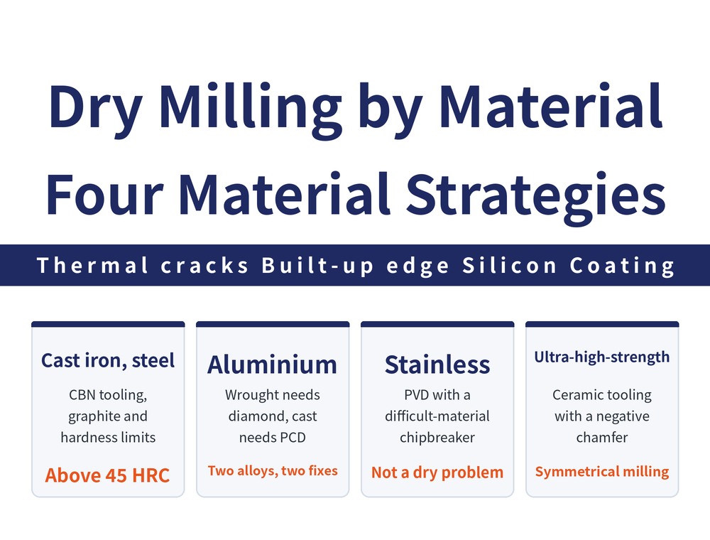
Milling was the first process where dry cutting proved better than wet, and the reason is not environmental: it is the thermal cracking caused by each insert entering and leaving the cut. But the bottleneck differs completely by material — cast iron and steel are limited by tool material thresholds, aluminium by built-up edge and silicon particles, stainless by coating choice, and ultra-high-strength steel by edge strength.
1. Why milling is where dry cutting succeeded first
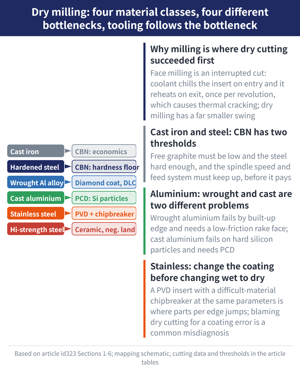
Coolant has a counter-productive effect in milling that it does not have in turning. Face milling is an interrupted cut: the insert is chilled as it enters the workpiece and heats up again as it leaves, once per revolution. That severe temperature swing generates alternating thermal stress inside the insert, which shows up as thermal cracking.
Dry milling still has a heating and cooling cycle, but the amplitude is far smaller, and what remains can be handled through tool material, cutter body design and geometry. That is why in milling, dry cutting is not merely acceptable — it can deliver better results than wet cutting, and it remains the most widely applied branch of dry machining. For the overall coolant decision, see how to choose cutting fluid.
2. Decide Whether to Use Coolant First: When to Turn It Off, When It Must Be Wet
Dry or wet is decided by the job, not by habit. The table below follows the ISCAR milling applications guide.
| Situation | Recommendation | Why |
|---|---|---|
| Heavy-duty milling of steel with indexable cutters | Coolant not recommended | It widens the temperature swing and promotes thermal cracks |
| Light high-speed milling of workpieces at HRC 45 and above | Use air cooling | Tool life actually increases once wet cooling is removed |
| Titanium, high-temperature superalloys, heat-resistant steel, special hard alloy cast iron | Must be wet | Friction and heat are extreme |
| Deep or narrow slots | Use coolant to flush chips | Better chip evacuation, less chip re-cutting |
| You want lubrication without flooding | MQL (Minimum Quantity Lubrication) | Its main job is lubrication; the part and chips stay almost dry |
When an edge fails, tell the two cases apart first: comb-like thermal cracks come from temperature swings, so the fix is to stabilize temperature—possibly by switching coolant off; a sagging, deformed edge means it is too hot, so slow down or cool harder. The two fixes are opposite.
If you do use coolant, it has to reach the cut: low-pressure flood coolant under heavy heat forms a vapor film on the tool and workpiece that traps the heat, so switch to high-pressure coolant aimed at the cutting zone.
3. Cast iron and steel: CBN has two thresholds
Cubic boron nitride (CBN, the hardest tool material after diamond) has both high heat resistance and high hot hardness, making it the mainstay for dry milling cast iron and hardened steel. Once economics are included, however, it comes with two explicit thresholds: free graphite content below 5% in grey and ductile iron, and steel hardness above 45 HRC, with machine spindle speed and feed system able to keep up. For the material itself, see the CBN and PCBN tooling guide.
| Material and operation | Cutting speed (m/min) | Feed (mm/rev) | Depth of cut ap (mm) |
|---|---|---|---|
| Grey iron, finishing | 1000–2000 | 0.2–0.3 | 0.3–0.4 |
| Grey iron, roughing | 1000–1500 | 0.4–0.5 | 1–3 |
| Hardened steel, finishing | 100–250 | 0.05–0.4 | 0.05–0.2 |
| Hardened steel, roughing | 60–100 | 0.2–0.4 | 0.5–1.5 |
The table gives reference ranges for CBN dry milling. These are not recommendations for a specific tool; always follow the insert catalogue and your machine conditions, and see the end mill cutting conditions guide for conversion. There is also a route that pushes speed much further: milling cast iron with ceramic or CBN fast enough to bring the cutting zone red hot, lowering the yield strength of the material. Cutting forces drop substantially and removal rates rise, and because most heat leaves with the chips, thermal distortion of the part is actually smaller. This route demands very high machine rigidity and spindle speed, and is a solution for a minority of production lines rather than a general rule.
4. Aluminium: wrought and cast are two different problems
Aluminium dry milling is often treated as one topic. It is really two, with different bottlenecks.
Wrought aluminium alloys (such as AlZnMgCu1.5 used in aerospace parts) mainly suffer from built-up edge. The answer is a low-friction rake face: a K10 carbide substrate with WC/C, diamond-like carbon or diamond coating all work. For identifying built-up edge against other wear modes, see the tool wear analysis guide.
Cast aluminium alloys (such as AlSi10Mg in engine components) do not fail by sticking — they fail on hard silicon particles. The silicon in cast aluminium is hard, and in multi-tooth interrupted cutting it repeatedly impacts the cutting edge. Carbide tooling then shows three symptoms: surface quality and accuracy drop noticeably after a certain number of parts, tool wear is severe with a tendency to vibrate, and thermal distortion affects accuracy as removal rate increases. The answer here is polycrystalline diamond (PCD) — low cutting force, low heat, stable in interrupted cutting, holding better surface roughness at the same parameters and keeping flank wear at a very low level. See PCD and diamond coating.
5. Stainless steel: change the coating before changing wet to dry
The common misreading with stainless is to ask whether dry cutting itself can work. In practice the governing variable is the coating and chipbreaker: at identical parameters, swapping a CVD-coated insert for a generic PVD one may not improve life at all, whereas moving to a PVD insert with a chipbreaker designed for difficult materials, run as dry roughing, is where parts-per-edge improves by an order of magnitude.
In other words, confirm the insert selection is right before judging whether dry milling is viable on stainless. Blaming dry cutting for what is a coating selection error is a common misdiagnosis. For coating positioning, see common tool coating materials.
6. Ultra-high-strength steel: ceramics and a negative chamfer
Ultra-high-strength steels rich in Ni, Cr and Mo, harder than 45 HRC and still tough, give short tool life and poor efficiency with ordinary carbide. The workable direction is dry milling with silicon nitride–alumina based ceramic tooling, using a negative chamfer to reinforce the edge and a single-tooth symmetrical face milling arrangement, which can hold surface roughness in the sub-micron range. For the classes and limits of ceramic tooling, see the ceramic cutting tool guide.
7. All four materials at a glance
| Material | Main bottleneck | Tooling direction | Precondition |
|---|---|---|---|
| Grey / ductile iron | Economics | CBN | Free graphite <5%, high-speed spindle |
| Hardened steel | Tool heat resistance | CBN | Above 45 HRC to be worthwhile |
| Wrought aluminium | Built-up edge | Diamond coating, DLC, WC/C | Low friction on the rake face |
| Cast aluminium | Silicon particles, chipping | PCD | Stability in interrupted cutting |
| Stainless steel | Coating and chip control | PVD with difficult-material chipbreaker | Verify insert selection first |
| Ultra-high-strength steel | Edge strength | Si3N4–Al2O3 ceramic | Negative chamfer, symmetrical milling |
If going fully dry is not realistic yet, there is a middle path: near-dry machining. A nozzle built into the rake face delivers a very small volume of high-pressure water mist that forms a cushioning layer at the tool–chip interface, reducing friction and helping chips break off. Fluid consumption is far below conventional flood cooling, and it also helps on difficult materials such as titanium alloys.
8. Frequently Asked Questions (FAQ)
Q: Is dry milling really better than wet milling?
In milling, usually yes. Coolant intensifies the heating and cooling cycle each time the insert enters and leaves the cut, causing thermal cracks; dry milling has a much smaller temperature swing. It still requires the right tool material and geometry.
Q: Does dry milling cast iron always require CBN?
No. Whether CBN pays off depends on free graphite content and available spindle speed; where those conditions are not met, coated carbide can also be run dry, simply in a different speed range.
Q: Why separate wrought and cast aluminium?
The failure mechanisms differ. Wrought aluminium fails by built-up edge and needs a low-friction rake face; cast aluminium fails by chipping from hard silicon particles and needs an impact-resistant superhard material such as PCD.
Q: Dry milling stainless gives poor life — should I go back to wet?
Check the insert first. If the coating type and chipbreaker are wrong, wet will not be good either; parts-per-edge in dry roughing typically only pulls ahead after switching to a PVD insert intended for difficult materials.
This article is part of Dry Machining: The Complete Guide - Losing the Coolant, and How Five Processes and Three Techniques Cope; that guide shows how the whole topic fits together.
Published: 2026-08-26 | Last updated: 2026-10-19









