
How to Select Parting and Grooving Tools: Three Methods and a Process
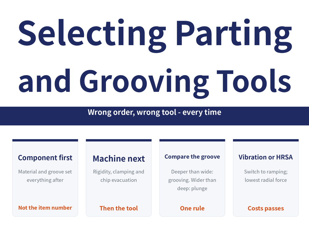
Most parting and grooving selection mistakes are not the wrong item number but the wrong order. The correct sequence is component and material, machine conditions, tool, how to apply, then troubleshooting. The machining method itself follows a simple rule: compare groove width with groove depth. Deeper than wide means multiple-pass grooving, wider than deep means plunge turning, and vibration or heat resistant super alloys point to ramping.
1. In What Order Are Parting and Grooving Tools Selected?
The common mistake is opening the catalogue first and only then discovering that the turret interface does not match or that chips cannot escape. Parting and grooving share the same five-stage selection framework as general turning (per Sandvik technical information): component and workpiece material, machine parameters, tool selection, how to apply, troubleshooting. The first two stages are constraints, the third is where you finally pick a tool, and the last two decide whether it performs. The same framework for general turning is covered in Turning Tool Selection Process.
| Stage | What this step decides |
|---|---|
| 1 Component and material | Operation type, groove size and quality demands |
| 2 Machine parameters | Stability, clamping, turret interface, chip evacuation |
| 3 Tool selection | Holder or blade, insert width, geometry and grade |
| 4 How to apply | Machining method, overhang, centre height, coolant |
| 5 Troubleshooting | Read wear and defects, then revise the earlier steps |
2. Which Three Things Must Be Fixed Before You Choose?
Catalogues usually split parting and grooving tools into shallow, medium and deep product lines, then subdivide by diameter or bore. The boundaries differ by brand, so treat the figures as manufacturer specifications only. The logic behind them is general: the deeper the cut, the worse the rigidity, and the blade section and insert seating design must change with it. Settle the three items below first and the catalogue step goes much faster.
| Item to fix | Content | What it determines |
|---|---|---|
| Operation type | Parting, external grooving, undercutting, face grooving, internal grooving, profiling | Tool family and insert shape |
| Groove geometry | Width, depth, bottom corner radius, tolerance and surface demands | Insert width, geometry and the machining method |
| Position and access | External or internal, part diameter or bore, overhang needed | Holder or blade size and rigidity class |
How the individual groove types actually differ is covered in Grooving Operations Guide.
3. Which Machine Conditions Restrict the Tool Choice?
Stage two is often skipped, yet it removes half the options outright. What matters is stability, power and torque (large diameters are especially torque hungry), component clamping, the turret interface, tool changing time and turret capacity, chip evacuation, and coolant supply (per Sandvik technical information). Note that chip evacuation is listed at machine level, not merely as an insert geometry issue. Parting chips can only retreat along the narrow slot the tool cut for itself, and if the machine cannot clear them no geometry will save the job, as explained in Parting Off Guide.
| Machine condition | What it rules out |
|---|---|
| Rigidity, power and torque | Usable insert width and metal removal per pass |
| Component clamping | Acceptable overhang and machining method |
| Turret interface and capacity | Holder type, and whether roughing and finishing can be split |
| Chip evacuation and coolant | Feasible groove depth, and the need for internal coolant |
4. How Do the Three Machining Methods Differ?
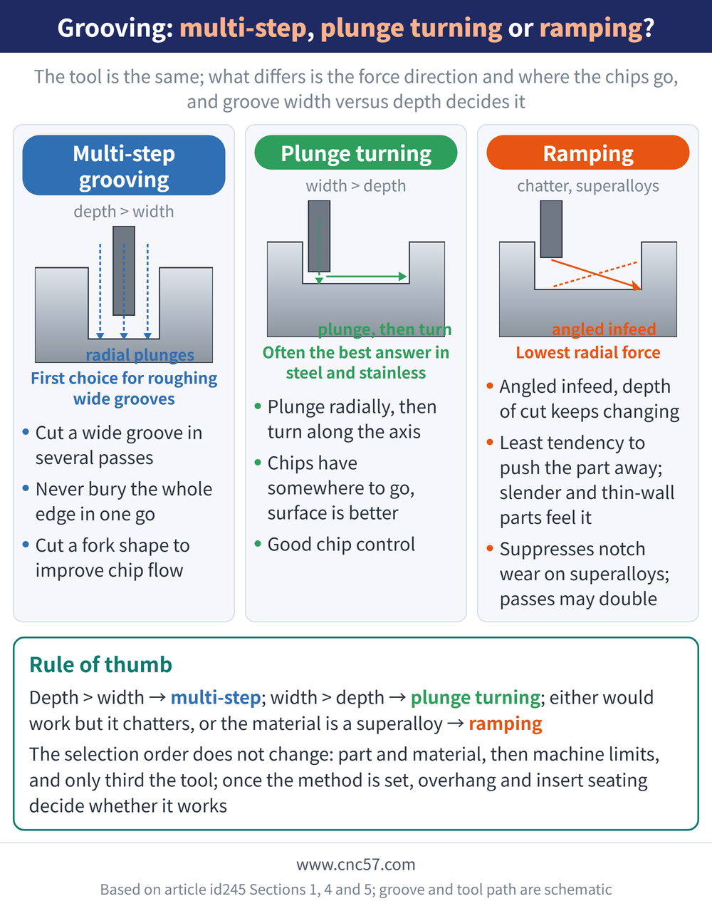
Once the tool is chosen, the same tool still offers three routes. Multiple-pass grooving cuts a wide groove in several passes; plunge turning feeds radially first, then turns sideways along the axis; ramping feeds at an angle so the depth of cut keeps changing. The difference lies not in the tool but in force direction and where the chip goes.
| Method | When it applies | Characteristics and benefits |
|---|---|---|
| Multiple-pass grooving | Depth greater than width | First choice for roughing wide grooves; fork shape aids chip flow |
| Plunge turning | Width greater than depth, steel and stainless | Often the best answer; good chip control |
| Ramping | Vibration must be avoided, heat resistant super alloys | Lowest radial force; the cost is roughly double the passes |
Once the method is fixed, overhang and insert seating decide whether it works in practice, as covered in Grooving Overhang and Insert Seating.
5. Does Width Versus Depth Really Settle the Method?
It does. This is the cleanest single rule in the whole process, and it can go straight onto the process sheet.
Depth > width → multiple-pass grooving (cut in stages so the whole edge is never buried at once)
Width > depth → plunge turning (turning sideways gives the chip somewhere to go, with a better surface)
Either would work but it chatters → ramping (per Sandvik technical information and the manufacturer technical guide)
Ramping is the third route, chosen for force rather than for speed. Angled infeed drives radial force to a minimum, so the part is pushed away less, which matters on slender or thin-walled work; the mechanism is covered in Anti-Vibration Tool Holder Guide. In heat resistant super alloys (HRSA) there is a second benefit: these materials and austenitic stainless steels tend to form notch wear at a fixed depth-of-cut line, and constantly varying the depth of cut is the accepted countermeasure, which ramping does by nature. Wear identification is covered in Tool Wear Analysis Guide, and reading failures in Parting and Grooving Troubleshooting.
6. Frequently Asked Questions (FAQ)
Q: What is the selection order for parting and grooving tools?
Component and workpiece material, machine parameters, tool selection, how to apply, then troubleshooting. The first two stages are constraints; only the third is where an item number is picked.
Q: How do I choose between multiple-pass grooving and plunge turning?
Compare groove width with depth: deeper than wide calls for multiple-pass grooving, wider than deep for plunge turning. Manufacturer technical guides state this rule explicitly.
Q: When should ramping be used instead?
When radial force must be kept low to avoid vibration, or in heat resistant super alloys to reduce notch wear; the cost is roughly double the number of passes.
Q: Can catalogue shallow, medium and deep classes be used as design limits?
No, those ranges belong to each manufacturer product line. Only the logic is general: the deeper the cut, the worse the rigidity, so blade and seating design must change.
For the full reading guide on this topic, see Insert Selection: A Complete Reading Guide.
For the full reading guide on this topic, see Turning: The Complete Guide.
Published: 2026-08-09 | Last updated: 2026-08-09









