
Parting and Grooving Troubleshooting: Wear, Surface, Chip Breaking and Vibration
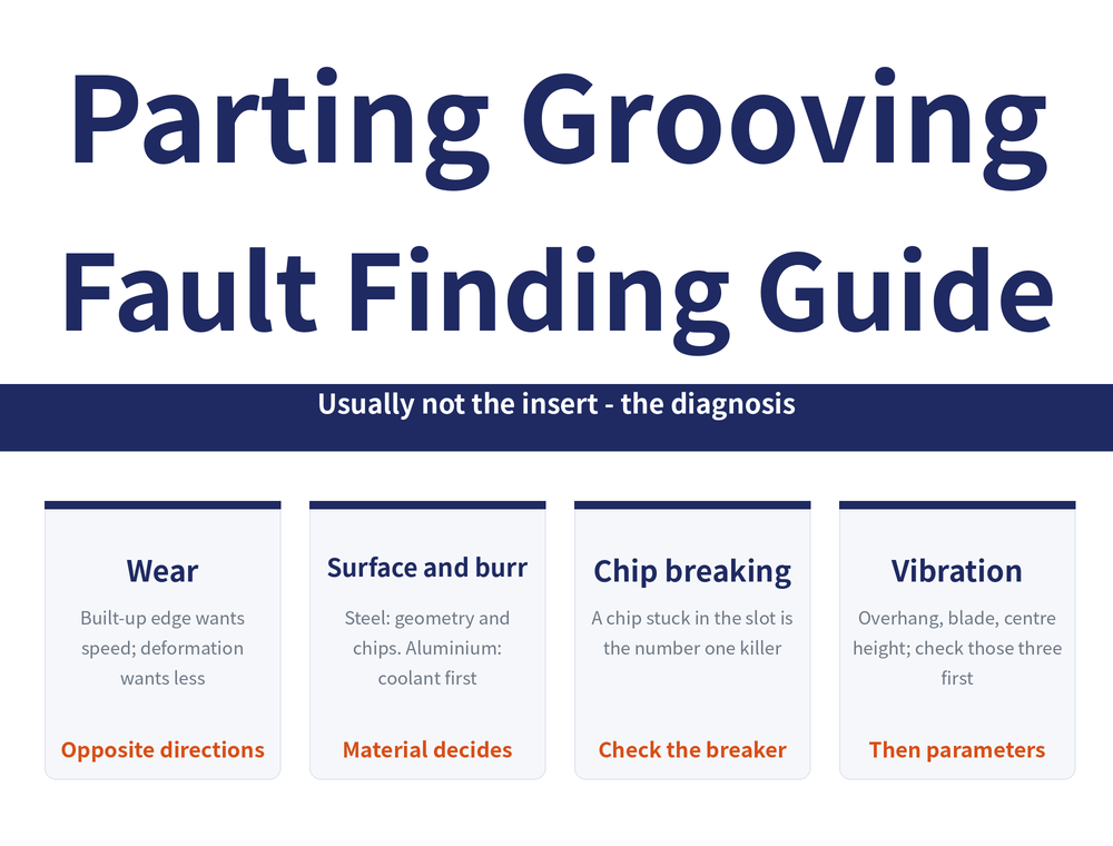
When parting or grooving goes wrong, the insert is usually not the problem — the diagnosis is. Poor surface on steel calls for a different geometry and better chip control, while on aluminium the coolant comes first; built-up edge wants more speed, plastic deformation wants less. This article splits the symptoms into wear, poor surface and burrs, poor chip breaking and vibration, one table each, plus the check that is missed most often.
1. Why parting and grooving faults need their own logic
A parting blade is narrow, the overhang is long, and the chip is trapped in the groove the tool has just cut, so the same symptom often has a different cause than in external turning. For general turning diagnosis see Turning Troubleshooting Guide, and for how each wear pattern looks and forms see Tool Wear Analysis Guide; this article covers only what is specific to parting and grooving. For the mechanics of parting see Parting Off Guide.
2. Wear: which pattern needs more speed, which needs less?
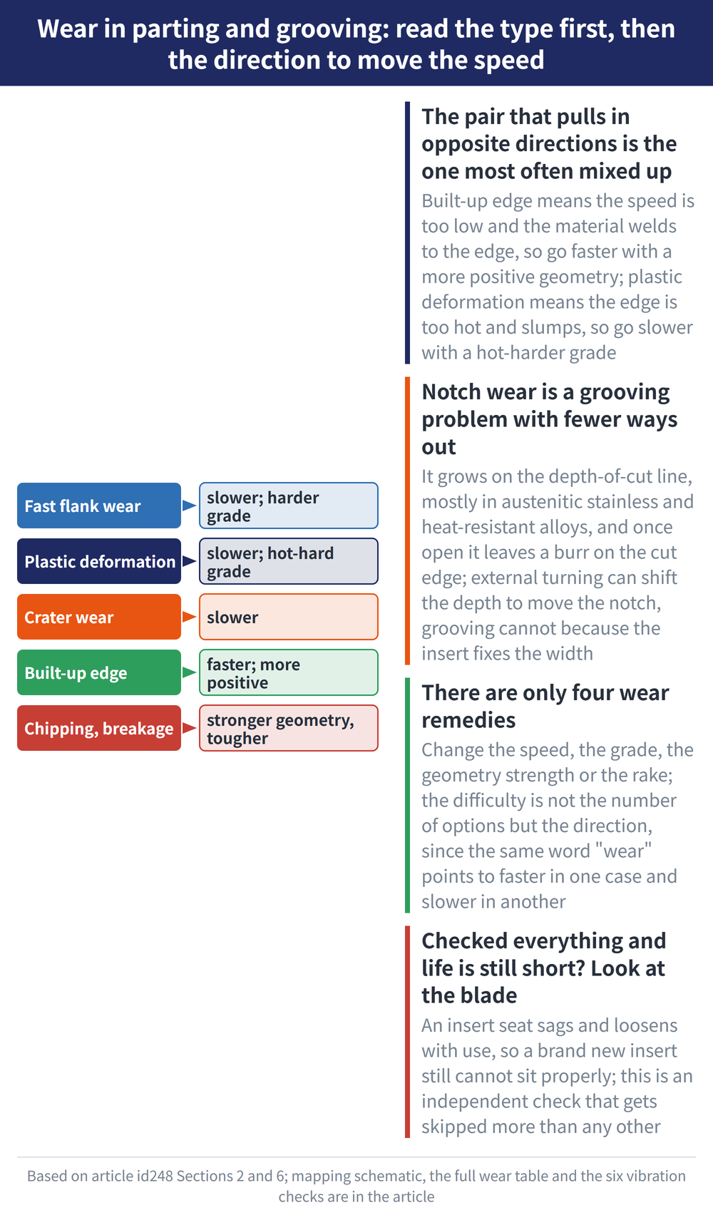
According to Sandvik technical information, the wear remedies come down to four moves: change speed, change grade, choose a stronger geometry, choose a more positive geometry. The hard part is the direction.
| Wear pattern | Direction | Why |
|---|---|---|
| Rapid flank wear | Lower speed; more wear-resistant grade | Hard particles abrade the edge |
| Plastic deformation | Lower speed; better hot hardness | The edge overheats and sags |
| Crater wear | Lower speed | Diffusion on the rake face |
| Built-up edge | Raise speed; more positive geometry | Speed too low, material sticks |
| Chipping | Stronger geometry, tougher grade | The edge cannot take the shock |
| Insert fracture | Stronger geometry; recheck data | Load beyond edge capability |
Grooving has one wear form of its own: notch wear, which grows at the depth-of-cut line, appears mostly in austenitic stainless steels and heat-resistant alloys, and raises burrs at the cut edge as it opens up. External turning can vary the depth of cut to move the notch, but in grooving the cut width is fixed by the insert, so only grade toughness and speed are left. For grade and insert choice see Grooving Tool Selection Guide.
3. Poor surface and burrs: steel and aluminium are not the same case
According to Sandvik technical information, poor surface quality in aluminium is listed as a problem class of its own: aluminium smears and forms built-up edge easily, so cutting data alone will not fix it — the sharpest geometry and a water-soluble oil made for the material are needed. Treating an aluminium surface like a steel one usually wastes the shift.
| Symptom | Possible cause | Remedy |
|---|---|---|
| Scratched groove walls | Chips not evacuated, poor chip control | Change geometry; use precision coolant tooling |
| Unstable roughness | Speed or feed off target | Recheck the recommended values |
| Visible tool marks | Clamping problem | Shorter stable tool; check clamping; wiper geometry |
| Smeared aluminium surface | Geometry not sharp enough | Sharpest geometry with good chip control |
| Smearing and built-up edge | Coolant not suited to aluminium | Water-soluble oil made for aluminium |
The pip and burr left at the centre when parting off is a separate matter of feed timing, covered in Parting Off Guide.
4. Poor chip breaking: the chip is trapped in its own groove
The chip has to leave through the groove just cut, and the deeper and narrower that groove is, the worse the escape route. A jammed chip first scores the wall, then damages the edge. According to Sandvik technical information there are four remedies.
| Remedy | How | When it applies |
|---|---|---|
| Raise the feed | Go up within the recommended range | Long stringy chips that will not curl |
| Change the geometry | Pick stronger chip control | Feed already at its limit |
| Use micro-stop (step) | Pause the feed briefly to break the chip | Deep grooves or profiling |
| Precision coolant | Coolant fed between edge and chip | Chips piling up in the groove |
How a chipbreaker steers the chip into a C shape is covered in Turning Chip Control Guide. When profiling with a grooving insert whose radius is not smaller than the profile corner radius, the contact arc grows and micro-stop is again needed to keep the chip short.
5. Vibration: six checks, starting with the free ones
Vibration rarely has a single cause, but the checks have an order. According to Sandvik technical information there are six of them; do the ones that cost nothing first, then the cutting data, and change tooling last.
| Order | Possible cause | Remedy |
|---|---|---|
| 1 | Tool clamped off centre | Reset the centre height |
| 2 | Tool overhang too long | Shorten tool and part overhang |
| 3 | Loose part or tool clamping | Use a more stable clamping |
| 4 | Tool in poor condition | Check the edge and the seat |
| 5 | Speed or feed off target | Recheck the values, then adjust |
| 6 | Geometry wrong for the job | Change to another geometry |
How long the overhang may be, and what a badly seated insert does, is covered in Grooving Overhang and Insert Seating. Only when all six checks are clean and it still chatters does an Anti-Vibration Tool Holder Guide solution come into play.
6. Still short tool life? Do not forget the blade itself
When tool life disappoints, most people blame the insert or the data first. According to Sandvik technical information the blade or holder itself is a separate check: a seat that has been in service a long time collapses and loosens, and even a new insert will not sit still. This step is the one usually skipped.
| Check | How to spot it | Remedy |
|---|---|---|
| Centre height | A pip left at the centre | Reset the centre height |
| Tool to part angle | Walls out of square, one-sided wear | Align the tool again |
| Blade condition | A new insert still will not lock | Inspect the seat, replace if needed |
| Cooling | Burn colours, blue chips | Move to precision coolant tooling |
How OD grooves, circlip grooves and face grooves differ in practice is covered in Grooving Operations Guide.
7. Frequently Asked Questions (FAQ)
Q: Why are the remedies for built-up edge and plastic deformation opposite?
Built-up edge comes from too little speed and material sticking to the edge, so raise the speed and use a more positive geometry; plastic deformation comes from an overheated edge, so lower the speed and pick a grade with better hot hardness.
Q: Why is notch wear harder to deal with in grooving?
Because the cut width is set by the insert width, the depth of cut cannot be varied to move the notch as it can in external turning, leaving only grade and cutting speed.
Q: What should be changed first for poor surface on aluminium?
Check first that the coolant is a water-soluble oil intended for aluminium and choose the sharpest geometry; cutting data alone will not stop aluminium from smearing.
Q: Chips will not break — what should be tried first?
Raise the feed within the recommended range first, then move to a geometry with stronger chip control, and only after that consider micro-stop and precision coolant tooling.
For the full reading guides on this topic, see Insert Selection: A Complete Reading Guide, Chip Control: A Complete Reading Guide and Vibration and Chatter: A Complete Reading Guide.
Published: 2026-08-09 | Last updated: 2026-08-09









