
High-Feed Milling (HFM): Principle, Tools and Applications
HFM (high-feed milling) pairs a very small axial depth of cut with a very large feed per tooth, buying material removal rate with sheer feed speed — the exact opposite of the traditional "deep cut, small feed" approach. Only two things make it work: the chip thinning effect, and a small lead angle that steers the cutting force into the spindle axis. This guide covers the principle, the tool features, and when to use HFM and when not to.
1. What HFM Is: Very Small Depth, Very Large Feed
HFM (High Feed Milling) is a roughing strategy: ap (axial depth of cut, how deep the tool steps down each pass) is kept very small, while fz (feed per tooth, the thickness each cutting edge takes per revolution) is opened up a long way.
Each pass removes a thin layer, but the feed speed is so high that MRR (material removal rate, the volume of material removed per unit time) still comes out ahead. The direction is the reverse of traditional roughing.
| Criterion | Traditional roughing | High-feed milling (HFM) |
|---|---|---|
| Axial depth of cut, ap | Large, taken in one deep bite | Far smaller than in ordinary milling |
| Feed per tooth, fz | Conservative | Clearly increased |
| Where the productivity comes from | Depth of cut | Feed speed |
| Main cutting force direction | Mostly radial, pushing the tool sideways | Mostly axial, pushing up into the spindle |
| What it demands from the machine | Spindle torque and overall rigidity | Feed axis speed and acceleration |
| Typical positioning | Rigid setup, clear the stock in one pass | Bulk stock removal, long overhang, limited rigidity |
The table gives typical direction only; follow the catalogue or the relevant standard — not measurements taken by this site.
2. Why It Works: Chip Thinning Plus Force Direction
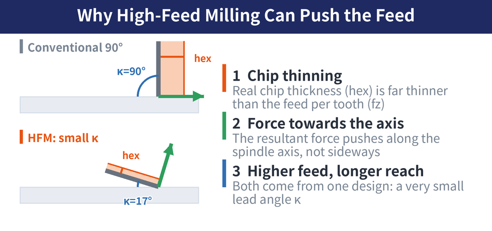
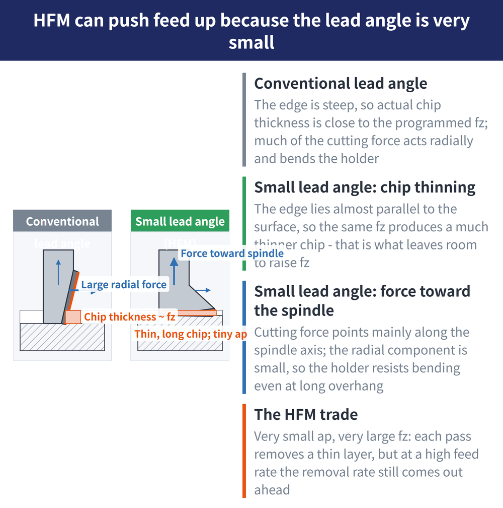
HFM dares to open up fz for only two reasons, and both come from one design feature: a very small lead angle (the tilt of the cutting edge relative to the workpiece surface, which sets where the chip goes and where the cutting force points).
1. The chip thinning effect. With a small lead angle the edge sits nearly parallel to the workpiece surface, so the chip actually cut is far thinner than the fz that was programmed. That is what leaves room to raise fz. For the mechanism and the compensation maths, see Chip Thinning and Feed Compensation.
2. Cutting force steered into the spindle axis. A small lead angle sends the resultant force mainly up along the spindle axis instead of sideways. Spindle and holder are stiffest in that direction, so vibration stays low and the tool can reach further.
In one line: chip thinning is what lets the feed grow, and axial loading is what lets the tool reach. Those two points are the whole of HFM; everything else follows from them.
Lower side force also lowers the chatter risk — see Milling Chatter: Causes and Solutions; for how overhang relates to tool deflection, see End Mill Length vs Deflection.
3. What an HFM Tool Looks Like: Every Feature Serves the Small Lead Angle
An HFM cutter is not an ordinary mill run faster; it is redesigned around the small lead angle, and every insert and body feature points at that.
| Feature | Why it is built that way |
|---|---|
| Small lead angle insert (curved edge or large-radius button style) | It generates both the chip thinning and the axial loading, so it is the core part of HFM |
| Only a short outer section of the edge does the cutting | It matches the very small ap; going beyond that section loses the small lead angle effect |
| Dedicated high-feed insert seat with a fixed tilt | The seat angle is the lead angle itself, so ordinary milling inserts do not interchange |
| Enlarged seat and clamping screw, widened seat support face | High feed means a hard hit per tooth; weak support loosens the insert before it chips |
| Large core diameter body, short flute length | Core diameter carries the axial load, and a short flute keeps deflection down |
| Shallow, wide chip gullets | Chips are thin and wide and arrive in bulk, so they have to clear fast |
The table gives typical direction only; follow the catalogue or the relevant standard — not measurements taken by this site.
4. How It Differs From an Ordinary Mill: The Lead Angle Sets the Job
All three are milling cutters; change the lead angle and both the force direction and the job change with it. For where each milling method sits, see Milling Methods Overview.
| Cutter | Lead angle and loading | Strength and price paid |
|---|---|---|
| Solid end mill | Peripheral edge close to perpendicular to the surface, force mostly radial | Cuts a square shoulder, but carries a high side load |
| General face mill | Larger lead angle, force part radial and part axial | Covers both face and shoulder |
| HFM cutter | Lead angle driven deliberately as small as possible, loading turned axial | Feed can be opened up, but it cannot cut a right angle |
The table gives typical direction only; follow the catalogue or the relevant standard — not measurements taken by this site.
5. When to Use HFM
HFM is a roughing productivity tool, not a universal strategy. The decision turns on two questions: does the feature need a right angle, and can the machine actually deliver the feed? Start with the cases that suit it.
| Suitable situation | Reason |
|---|---|
| Die and mould cavity roughing, bulk stock removal | Thin layered passes at high feed usually cut the total roughing time noticeably |
| Deep pockets and deep cavities | The force runs axially, so vibration stays manageable even with long overhang |
| Roughing difficult-to-cut material (superalloys, hardened steel) | Thin chips and short edge contact spread the heat load; for the material-side strategy see Titanium and Superalloy Machining Guide (ISO S) |
| Machine rigidity is limited but productivity still matters | Productivity is not bought with side-load rigidity, which suits older or smaller machines |
The table gives typical direction only; follow the catalogue or the relevant standard — not measurements taken by this site.
6. When Not to Use HFM
In the four cases below, forcing HFM only costs tooling or accuracy; going back to a traditional strategy is faster:
| Unsuitable situation | Reason |
|---|---|
| Square shoulders and straight side walls needed | A small lead angle cannot produce a right angle and leaves a sloped floor transition |
| Finishing work where surface quality matters | HFM is a roughing strategy; scallop height and surface finish are not what it optimises for |
| Wanting one deep axial pass to clear everything | Once ap exceeds the effective cutting section the insert simply chips; there is no compromise setting |
| Machine feed speed or acceleration cannot keep up | HFM trades feed for productivity, so a slow machine leaves only the drawback of a shallow cut |
The table gives typical direction only; follow the catalogue or the relevant standard — not measurements taken by this site.
Do not apply generic cutting speed and feed per tooth values; decide them from the tool catalogue and a trial cut, with the calculation method in End Mill Cutting Conditions Guide.
Last updated: 2026-08-08
7. Frequently Asked Questions (FAQ)
Q: Which is more productive, HFM or traditional roughing?
It depends on the machine. When feed speed and acceleration can keep up, HFM usually gives the higher material removal rate; on a machine that cannot reach those feeds, a traditional deep cut pays back better.
Q: Can an ordinary end mill or face mill be used for HFM?
No. The small lead angle and its dedicated insert seat are the principle itself, and an ordinary cutter cannot produce that angle — forcing the feed up only chips the edge.
Q: Can HFM really run with a long overhang?
Relatively, yes, because the force runs along the spindle axis and side deflection stays small. Still step the cut up gradually and confirm vibration and size rather than scaling short-overhang values directly.
Q: What cutting speed and feed per tooth should HFM run at?
There are no universal values; work from the recommended range in the tool catalogue and confirm with a trial cut. For the conversion method, see the End Mill Cutting Conditions Guide.
For the full reading guide on this topic, see Insert Selection: A Complete Reading Guide.









