Drilling Parameters Guide: Cutting Speed, RPM & Feed
Drilling parameters are central to machining efficiency, tool life and hole quality. The main ones are cutting speed (vc), spindle speed (n) and feed (f), tuned to material, drill diameter and tool type — carbon steel, stainless, aluminum and titanium each have different speed ranges and feed factors. With the feed factor (G), drill factor (T) and holding factor (C), you can build a complete model to set conditions precisely.
1. Why Parameters Matter
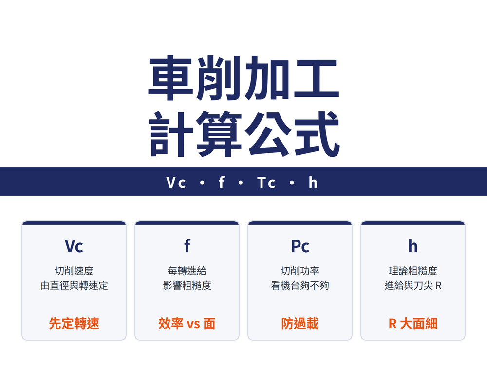
Hole quality depends mainly on cutting speed (vc), spindle speed (n) and feed (f) — together they set efficiency, tool wear and hole accuracy.
| Parameter | Meaning | Main effect |
|---|---|---|
| Cutting speed vc | Edge surface speed vs work (m/min) | Tool wear, cutting heat |
| Spindle speed n | Revolutions per minute (min⁻¹) | Efficiency, surface quality |
| Feed f | Feed per revolution (mm/rev) | Cutting force, evacuation, accuracy |
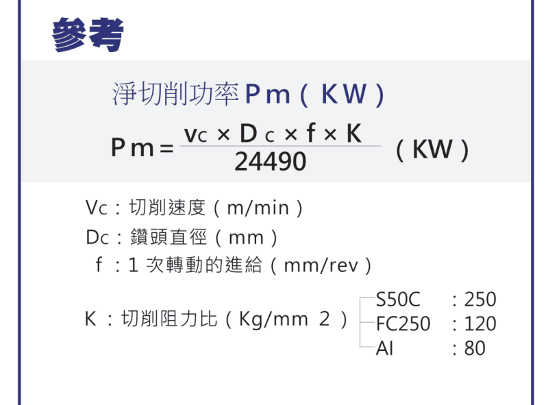
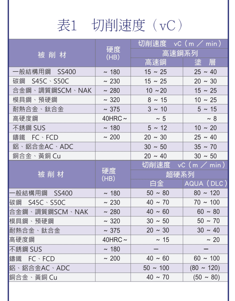
2. Cutting Speed (vc) by Material
Cutting-speed tendencies and starting references by material are below. The starting references are typical ranges for HSS drills; for carbide drills follow the catalog. Actual values still come from calculation and the tool catalog:
| Material | Cutting-speed tendency | Starting reference (HSS drill) |
|---|---|---|
| Carbon steel | Medium | Follow the drill catalog |
| Stainless steel | Lower (gummy, work-hardening) | About 8–24 m/min (typical); do not feed too lightly |
| Aluminum alloy | Higher | Much higher than steel; varies widely by drill material, follow the catalog |
| Titanium alloy | Low (poor heat conduction, heat build-up) | Ti-6Al-4V about 9–11 m/min (typical) |
| Cast iron | Low speed, heavy feed | Below 200 HBS, feed about twice that for mild steel of the same diameter |
※ For dry machining, cutting speed usually drops to about 70–80% of the wet value. For what goes wrong when drilling each material and how to choose the drill, see the drilling section of the stainless steel, cast iron, aluminum and non-ferrous and titanium and superalloy guides.
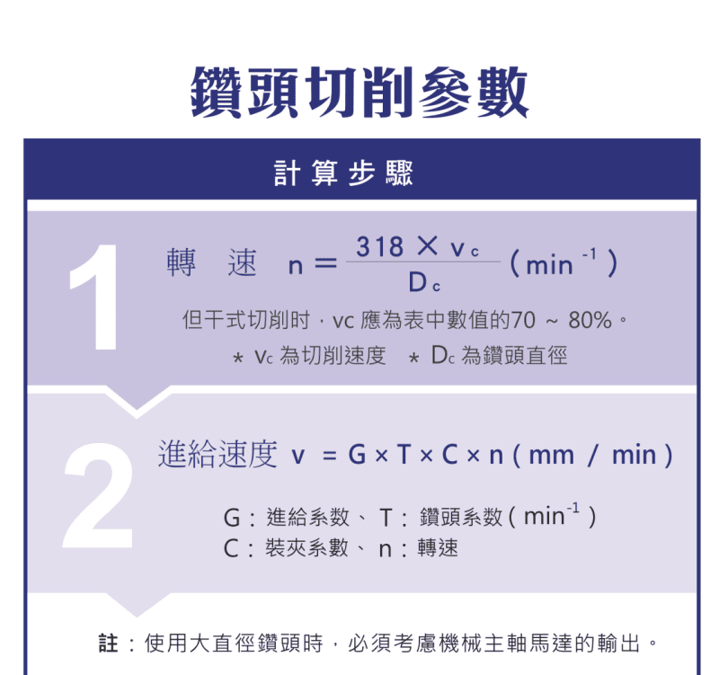
3. Spindle Speed (n) Calculation
Convert cutting speed and drill diameter to spindle speed with the common engineering approximation: See Drilling Parameter Conversion: RPM & Feed by Diameter for details.
n = 318 × vc ÷ Dc
| Symbol | Meaning |
|---|---|
| n | Spindle speed (min⁻¹) |
| vc | Cutting speed (m/min) |
| Dc | Drill diameter (mm) |
So at a given cutting speed, a smaller diameter needs a higher rpm, a larger diameter a lower rpm. For the full vc / n / vf / cycle-time derivation, see the Drilling Formula Guide.
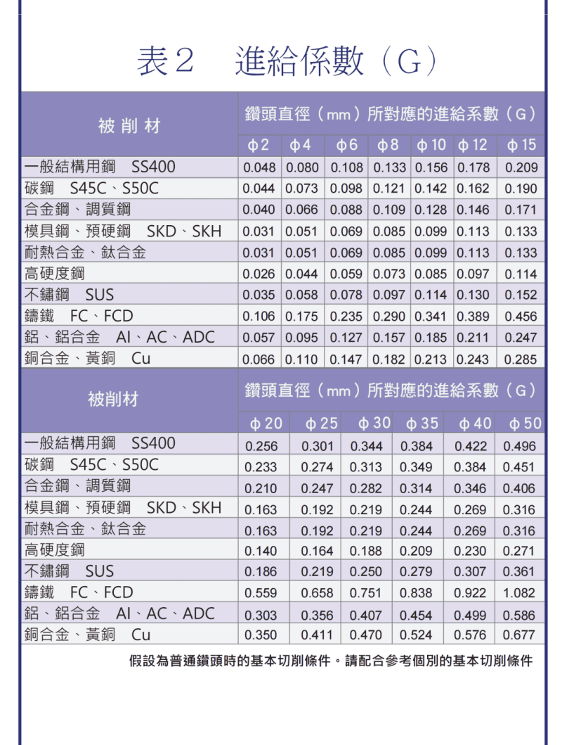
4. Feed (f) and Feed Rate (Vf)
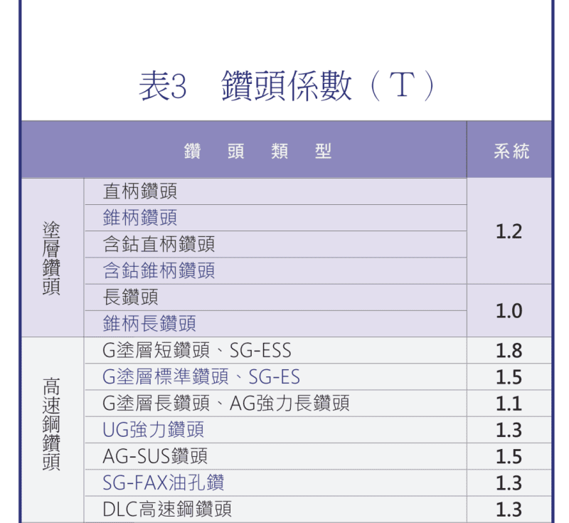
Feed rate can be estimated with a factor model:
Vf = G × T × C × n
| Symbol | Meaning |
|---|---|
| G | Feed factor (by material and diameter) |
| T | Drill factor (by tool type, e.g. coated / carbide) |
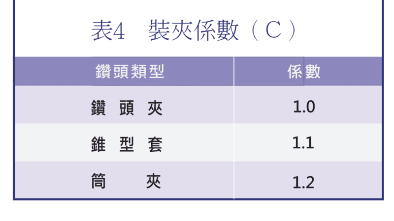
| C | Holding factor (by clamping method) |
| n | Spindle speed |
5. Cutting Power and Spindle Load
Use a power formula to assess machine load and avoid spindle overload:
Pm = vc × Dc × f × K
K is a material-related proportionality factor. Power assessment helps confirm the machine can handle the job before large-diameter or deep-hole drilling.
6. Material vs Machining Conditions
| Situation | Recommended direction |
|---|---|
| High-hardness material | Lower vc and f |
| Soft material | vc and f can be raised |
| Different drill types | Apply different factors (G / T / C) |
7. Factor Application and Holding Rigidity
The three factors map to material, tool and holding. The holding-rigidity order (high to low) is typically:
| Factor | Basis |
|---|---|
| Feed factor G | Varies with material and diameter |
| Drill factor T | Coated vs carbide drills, etc. |
| Holding factor C | Rigidity: collet > taper sleeve > drill chuck |
8. Setting the Conditions
The workflow: pick cutting speed by material → compute rpm from diameter → control feed precisely with the factors → check cutting power to avoid spindle overload. Set conservatively for hard materials, more aggressively for soft ones, then fine-tune by chip and wear behavior. For reading chips, see Drill Chip Formation Guide.
FAQ
Q: How do I calculate drill rpm?
Use the common approximation n = 318 × vc ÷ Dc, where vc is cutting speed (m/min) and Dc is drill diameter (mm). At a given vc, a smaller diameter needs a higher rpm.
Q: How do I pick cutting speed by material?
Roughly: aluminum highest, carbon steel medium, stainless lower, titanium lowest. With HSS drills, stainless runs about 8–24 m/min and titanium (Ti-6Al-4V) about 9–11 m/min. Drop to about 70–80% for dry machining, and set actual values from the tool catalog.
Q: What are the factors in feed rate Vf?
Vf = G × T × C × n. G is the feed factor (material and diameter), T the drill factor (tool type), C the holding factor (clamping method), and n the spindle speed.
Q: Does the holding method affect machining?
Yes. Higher holding rigidity tolerates higher feed and cutting force. A common order is collet > taper sleeve > drill chuck; with low rigidity, set feed conservatively.
For the full reading guide on this topic, see Machining Calculation Reading Guide.
This article is part of Drill Bits: The Complete Guide - Start From Depth-to-Diameter, Then Pick the Drill and Set the Conditions; that guide shows how the whole topic fits together.
Published: 2026-03-19 | Last updated: 2026-10-31