
How to Machine Grooves: OD Grooves, Circlip Grooves and Face Grooves
Grooving is not one operation. On an outside diameter, whether the groove is deeper or wider decides single-pass versus multiple-pass. For a circlip, the groove size is back-calculated from a standard dimension table. On a face, the blade has to be curved, the curve has to suit the groove diameter, and the machining direction cannot be reversed. This article covers all three cases and where each one goes wrong.
1. Why do three groove types need three approaches?
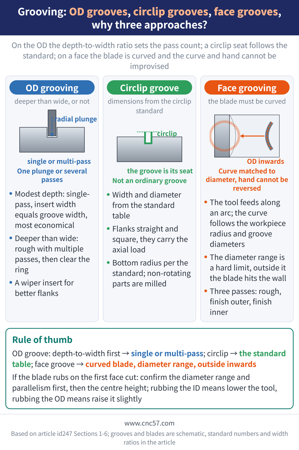
The word grooving covers very different jobs: a groove on an outside diameter, a groove on a face, or a seat for a circlip (a spring retaining ring snapped into a groove to stop a part moving axially). This article splits them into three cases: OD grooving decides pass count from the depth-to-width ratio; circlip grooves follow a standard; face grooving uses a curved blade whose curve and direction cannot be improvised. For parting mechanics see Parting Off Guide, and for the selection order see Grooving Tool Selection Guide.
2. OD grooving: one plunge or several passes?
OD grooving starts with one question: is the groove deeper than it is wide? When depth is modest, single-pass grooving (insert width equals groove width, one plunge to depth) is the most economical route; when depth exceeds width, rough with multiple-pass grooving instead, stepping across the groove and then clearing the remaining ring in one final pass (per Sandvik technical information). The full comparison is in Grooving Tool Selection Guide.
| Method | When to use it | What it gives |
|---|---|---|
| Single-pass grooving | Groove width within insert width range | Most economical high-productivity method |
| Multiple-pass grooving | Rough grooving where depth exceeds width | Best method for rough grooving |
Side-wall quality can be pushed one step further: a grooving insert with a wiper edge gives a very high surface quality on the groove flanks (per Sandvik technical information); achievable tolerances follow the tool catalogue. Chips jamming in a narrow groove are the most common failure mode, see Turning Chip Control Guide.
3. Chamfered groove corners: stock insert or tailor made?
There are two ways to produce a chamfer at the groove corner (per Sandvik technical information); the difference is who defines the chamfer shape, and which one pays off at what batch size. For how the nose radius itself behaves see Turning Tool Nose Radius Guide.
| Approach | Where the chamfer comes from | Trade-off |
|---|---|---|
| Stock insert | Formed by the insert nose radius | Low cost, shape limited by stock geometry |
| Tailor made insert | Exact chamfer ground into the insert | Higher one-off cost, pays off in volume |
4. Why can a circlip groove not be treated as an ordinary groove?
Circlips are common on shafts and axle components (per Sandvik technical information). The difference from an ordinary groove is that its dimensions are not chosen freely but back-calculated from the circlip standard: DIN 471 for external rings on shafts, DIN 472 for internal rings in bores (DIN is the German standards institute).
| Requirement | Why |
|---|---|
| Width and diameter from the table | The ring is a standard part, the groove is its seat |
| Flanks straight and square to the axis | Flanks carry the axial load; skew pushes the ring out |
| Bottom radius per the standard | An oversized radius stops the ring seating |
Tooling can be a three-edge or two-edge grooving insert; three-edge suits narrower grooves and is the most economical choice. Circlip grooves inside a bore have their own inserts and boring bars, where overhang and insert seating become the real limits, see Grooving Overhang and Insert Seating.
An easily missed branch point: if the circlip groove sits on a non-rotating part such as a housing, turning-type grooving logic does not apply and a milling cutter should be used instead (per Sandvik technical information).
5. Why is a face grooving blade curved?
Face grooving cuts a ring-shaped groove axially into the end face of a part. The tool feeds along an arc, so the blade must be curved, the correct curve depends on the workpiece radius, and selection has to consider both the inner and outer diameter of the ring groove (per Sandvik technical information). In other words one tool fixes both the curve and the hand, and both follow the machine set-up and the direction of workpiece rotation.
The diameter range is a hard limit: a blade curve is designed for one band of groove diameters. If the first-cut diameter falls outside it, the blade hits the groove wall on plunge and blade, insert and workpiece can all be scrapped together.
| Decision | Depends on | Cost of getting it wrong |
|---|---|---|
| Blade curve (A or B) | Workpiece radius, groove inner and outer diameter | Wrong curvature rubs the groove wall |
| Tool hand (right or left) | Machine set-up, spindle rotation direction | Cutting direction does not match the edge |
Direction cannot be reversed either: a face groove should be machined from the largest diameter progressively inwards, which gives the best chip control (per Sandvik technical information); interchangeable blades let standard tools replace non-standard ones.
6. How are the three face grooving passes split, and what if the blade rubs?
Roughing and finishing a face groove takes three passes rather than two, because both the inner and the outer radial face have to be finished to size (per Sandvik technical information).
| Pass | What it does | Watch out for |
|---|---|---|
| First pass (roughing) | Rough the groove within the allowed range | Always from largest diameter inwards; poorer chip breaking |
| Second pass (finish outer) | Turn inwards from the outside to finish the OD face | Cutting width 0.5-0.8 times insert width |
| Third pass (finish inner) | Finish the inner diameter to size | Same as the second pass |
The most common first-cut failure is the blade rubbing the workpiece: the causes behind both symptoms are almost identical, wrong diameter range, tool not parallel to the axis, centre height not checked, yet the remedies are opposite.
| Symptom | Remedy |
|---|---|
| Rubbing on the inner diameter | Lower the mounting height accordingly |
| Rubbing on the outer diameter | Raise the mounting height slightly |
Confirm the diameter range and parallelism first, then touch centre height; for its effect see Grooving Overhang and Insert Seating, and for reading other failures see Parting and Grooving Troubleshooting.
For the full reading guide on this topic, see Turning Toolpaths: The Complete Guide.
7. Frequently Asked Questions (FAQ)
Q: Should a groove deeper than it is wide be single-pass or multiple-pass?
Rough it with multiple-pass grooving: step across the groove, then clear the remaining ring in one pass. Use single-pass grooving when depth is modest.
Q: What sets the width and diameter of a circlip groove?
The circlip standard dimension table sets them: DIN 471 for shafts, DIN 472 for bores, with the drawing as the governing figure.
Q: Can a face groove be machined from the inner diameter outwards?
Not advisable. A face groove should be machined from the largest diameter inwards, because that direction gives the best chip control.
Q: What should be done when a face grooving blade rubs the workpiece?
Check first that the first-cut diameter is inside the blade range and the tool is parallel to the axis; lower the mounting height if it rubs the inner diameter, raise it if it rubs the outer.
For the full reading guide on this topic, see Insert Selection: A Complete Reading Guide.
Published: 2026-08-09 | Last updated: 2026-08-09









