
Three Things That Wreck a Grooving Tool: Overhang, Blade and Insert Seating
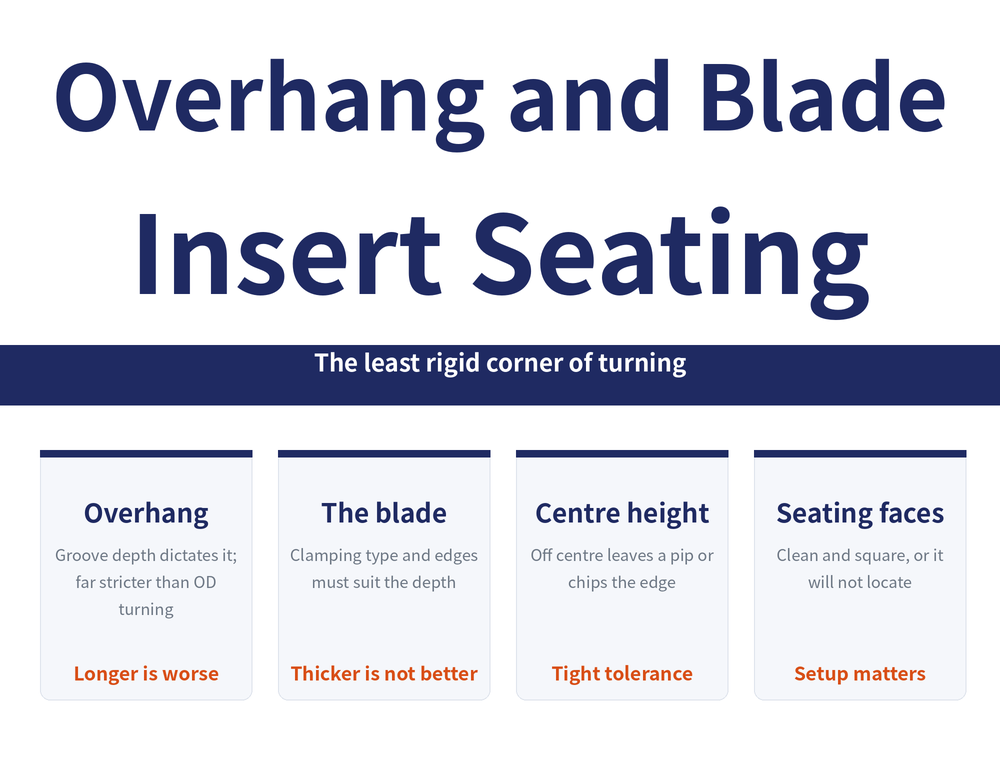
Parting and grooving is the least rigid corner of turning: the blade is thin, the overhang is dictated by groove depth, and there is almost no side support. What decides success is usually not the insert grade but three setup issues — how far the tool may stick out, which blade to pick, and whether the insert sits true in its seat. This article turns all three into principles you can judge by.
1. Why Is Overhang Harder to Control Than in OD Turning?
In external turning you gain rigidity simply by pulling the shank back; in parting and grooving you have no such freedom. For stability, tool overhang (the length the tool projects from the clamping face to the cutting edge) should always be as short as possible, but parting and grooving must also account for depth of cut and groove width, which means stability sometimes has to be sacrificed for accessibility (per Sandvik technical information). That is the difference: in OD turning you choose the overhang, in grooving the groove depth chooses it for you. Add a thin blade and a cutting force carried almost entirely on one side, and the same bar tolerates far less overhang in grooving than in turning. For the whole operation see Parting Off Guide, and for the selection order see Grooving Tool Selection Guide.
2. What Actually Sets the Overhang Limit?
Cantilever deflection is proportional to the cube of the projecting length (y = FL³ / 3EI): double the overhang and, at the same cutting force, deflection grows roughly eightfold (per Cutting Tool Engineering on boring bar deflection).
There is no universal multiplier to copy. Catalogues express the limit as a multiple of insert width or of blade height, and the figure swings widely with material and construction; what stays constant is the direction of judgement.
| Factor | What longer overhang does | What to do |
|---|---|---|
| Projecting length | Deflection worsens as a cube | Set just enough for the depth |
| Bar material | Steel vibrates first | Damped or carbide bars allow more; check the catalogue |
| Cross-section | Smaller section is softer | Use the largest section that fits |
| Internal work | Bore size caps bar diameter | Stay tighter than for internal turning |
If it cannot be shortened and still chatters, move to a tooling fix, see Anti-Vibration Tool Holder Guide; for bars see Boring Tool Holder Selection Guide.
3. Deep, Medium or Volume Parting: How Many Edges?
The first level of holder classification is not the brand, it is the parting depth (per Sandvik technical information).
| Situation | First choice |
|---|---|
| Deep parting | Spring-clamped blade with single-edged insert |
| Medium parting | Holder with double-edged insert |
| Economical volume parting | Three-edged insert |
The direction is clear: the deeper the cut, the more you move toward a single edge; only cost per part pushes you toward more edges. Screw-clamped holders made for three-edged inserts have their own profile: very small insert widths are possible, indexing tolerances are extremely tight, and one holder covers every width, at the cost of a limited depth capacity (per Sandvik technical information). For the operation types see Grooving Operations Guide.
4. Screw-Clamped or Spring-Clamped Blade?
Once the edge count is fixed, the second level is how the blade clamps. Each type wins somewhere (per Sandvik technical information).
| Criterion | Screw-clamped | Spring-clamped |
|---|---|---|
| Rigidity | Standard | Higher |
| Groove depth | Deep grooves | Shallow grooves |
| Adjustability | Overhang and insert width adjustable | Not adjustable |
| Feed direction | Radial only | Radial and axial |
| Workable diameter | Larger | Smaller |
| Insert position | Both blade ends | One end only |
| Indexing speed | Faster | Standard |
Need depth, larger diameters or an adjustable overhang: go screw-clamped. Need rigidity and axial feed on shallow grooves: go spring-clamped. Either way the general holder rules hold: the shortest possible overhang, the largest holder, the largest height dimension, the largest blade width.
5. What Does a 0.1 mm Seating Error Do?
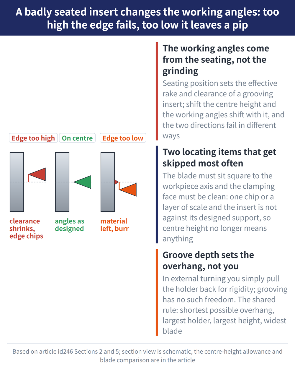
This is the step most often treated as "just bolt it on", yet it carries the hardest rule of the three: centre height deviation must not exceed ±0.1 mm (±0.004 in, per Sandvik technical information). The effective rake and clearance of a grooving insert are set by where it sits, so a shift in centre height shifts the effective angles, and each direction fails in its own way.
| Deviation | Consequence |
|---|---|
| Edge set too high | Clearance is reduced; the edge rubs and fractures |
| Edge set too low | Material is left at the centre, that is, a burr |
Two more positioning items get skipped just as often: the blade must sit square to the workpiece axis, and the clamping faces must be clean. One chip or a film of dried coolant on a seating face means the insert is not resting on the support surface it was designed for, and that ±0.1 mm becomes meaningless. For angle definitions see Turning Tool Rake and Clearance Angles; when things already go wrong see Parting and Grooving Troubleshooting.
6. How Do Insert Orientation and Nose Radius Pair Up?
Insert orientation comes in three forms according to the entering angle: right hand (R), neutral (N) and left hand (L). A holder mounted at 90° brings two benefits: perpendicular machined surfaces and reduced vibration (per Sandvik technical information). Nose radius is another trade-off with no outright winner.
| Choice | What you gain | What you pay |
|---|---|---|
| Small nose radius | Smaller burr, better chip control | Lower feed rate |
| Large nose radius | Higher feed rate, longer tool life | Burr and chip control give way |
If the burr on the parted face matters, go small; if volume output matters, go large. For the full logic see Turning Tool Nose Radius Guide.
7. Frequently Asked Questions (FAQ)
Q: Is there a universal overhang multiplier for grooving tools?
No. The rule is as short as possible, but groove depth limits you in return; the real ceiling depends on blade material, section and the catalogue, and grooving tolerates less overhang than a turning bar of the same size.
Q: How far off centre height is acceptable?
No more than ±0.1 mm (±0.004 in, per Sandvik technical information). Too high reduces clearance so the edge rubs and fractures; too low leaves a residual burr at the centre.
Q: Screw-clamped or spring-clamped blade for deep grooves?
Deep grooves favour the screw-clamped type, with adjustable overhang and insert width plus a larger workable diameter; the spring-clamped type is more rigid and allows axial feed, but suits shallow grooves.
Q: Should the nose radius be large or small?
A small radius gives a smaller burr and better chip control but a lower feed rate; a large radius gives better feed rate and tool life. If the parted face burr matters, choose small.
For the full reading guide on this topic, see Insert Selection: A Complete Reading Guide.
Published: 2026-08-09 | Last updated: 2026-08-09









