
How to Part Off: Why Trouble Starts at the Center
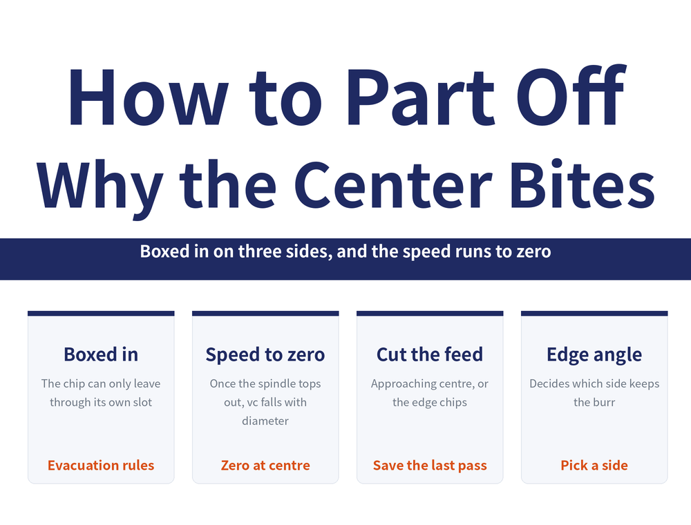
Parting off is hard for two reasons: the chip can only escape through the narrow slot the tool just cut, and cutting speed falls as the edge approaches the workpiece center. Once spindle speed hits the machine limit, cutting speed drops with diameter toward 0 m/min at center, so the surface degrades and the edge chips more easily. This article explains the geometry, then covers when to cut feed, edge line angle and burr, and bar versus tube.
1. How is parting off different from OD turning?
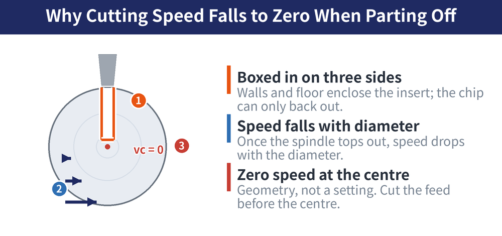
In outside diameter (OD) turning the nose touches material on one side only and the chip can be thrown clear; a parting blade, once engaged, is enclosed by both groove walls and the groove bottom, leaving one route out — back along the narrow slot. Chip evacuation is therefore the key factor in parting (per Sandvik technical information): the insert geometry must first narrow the chip so it curls into a spring shape narrower than the slot. When evacuation fails the chain follows: jamming, poor surface, chip packing, tool breakage. For chipbreaker fundamentals see Turning Chip Control Guide, and for tool choice see Grooving Tool Selection Guide.
| Item | OD turning | Parting off |
|---|---|---|
| Chip route | Free to clear the tool | Back out along the slot only |
| Enclosure | One face in contact | Two walls plus bottom: three sides |
| Deeper cut | Cutting force rises | Force and overhang worsen together |
2. Why does cutting speed fall to zero at center?
Cutting speed is the relative surface speed between edge and workpiece, set jointly by diameter and spindle speed. OD turning mostly runs constant surface speed, so spindle speed rises automatically as diameter shrinks; parting instead drives continuously toward center, with diameter shrinking all the way to zero. Once spindle speed reaches the machine limit it cannot compensate further, so cutting speed falls linearly with diameter and in theory reaches 0 m/min at center (per Sandvik technical information). This is geometry, not a machine fault. For the formulas see Turning Machining Formulas.
vc = π × D × n ÷ 1000
vc is cutting speed (m/min), D the instantaneous workpiece diameter (mm), n the spindle speed (rpm). Once n is capped it becomes a constant, so vc is simply proportional to D.
| Diameter D (mm) | vc (m/min) | Edge condition |
|---|---|---|
| 60 | 565 | Cutting normally |
| 40 | 377 | Falling |
| 20 | 188 | Low |
| 5 | 47 | Close to rubbing |
| 0 | 0 | No cutting action |
The table fixes n at 3000 rpm to show the trend; it is not a cutting condition recommendation.
3. When should the feed be reduced?
At very low speed the edge stops cutting and starts squeezing and rubbing. Load on the nose becomes unbalanced, built-up edge (BUE, workpiece material welding and piling up on the cutting edge) forms readily, surface finish degrades and the pip grows. The remedy is to cut feed before you get there: about 2 mm from center, drop to the tool's minimum recommended feed (in the order of 0.05 mm/r), or reduce it by 50–75% (per Sandvik technical information; Walter and YG1 publish similar guidance, and actual values follow the tool catalogue). For reading the symptoms see Parting and Grooving Troubleshooting.
| Effect of the final feed drop | Reason |
|---|---|
| Balances nose load | Load not concentrated on one point |
| Less vibration | Lower force, less chatter risk |
| Longer tool life | Exit is where edges break most |
| Smaller burr | Small pip, less deburring time |
4. Where does the pip at the center come from?
The part is not purely cut free: centrifugal force keeps pushing the separated side away, so the tool leaves a small stub at center, the burr or pip. Physics will not remove it; only geometry can reduce it. Edge line angle (the inclination of the cutting edge relative to the radial direction) is the main lever, and it is a trade-off: a larger angle leaves a smaller burr but deflects chip flow and weakens chip control; a near-neutral insert leads the chip straight out of the slot for better control and life, at the cost of a more visible pip. Center height error also creates burrs; see Grooving Overhang and Insert Seating.
| Edge line design | Burr | Chip control and life |
|---|---|---|
| Larger angle | Smaller | Worse, chip flow deflected |
| Near neutral | More visible | Better, chip led out of slot |
| Right hand or left hand | Sets which side keeps it | Depends on feed direction |
5. Do bar and tube part off the same way?
Same tool, different problems. Solid bar is cut all the way to center, so speed decay and the center pip both occur and the final feed drop is mandatory. A tube is a ring wall: the cut ends once the wall is pierced and there is no true center, but the edge enters and exits every revolution and the thin wall is not rigid, so it is easily pushed away into vibration and distortion. The feed reduction rule applies to tubes as well (per Sandvik technical information), and an angled edge avoids leaving a complete residual ring. For the groove itself see Grooving Operations Guide.
| Item | Solid bar | Tube and thin wall |
|---|---|---|
| At the exit | Reaches center, vc toward 0 | Ends when the wall is pierced |
| Main risk | Center burr, edge breakage | Entry and exit shock, distortion |
| Edge line choice | Angled edge reduces the pip | Angled edge avoids a ring |
6. Four things that keep parting off stable
Four basics make the operation stable. Keep overhang short: parting evacuates chips poorly, so the same bar tolerates far less overhang than in OD turning, though accessibility sometimes forces a rigidity compromise. Keep center height deviation within about ±0.1 mm (per Sandvik technical information). Keep cutting width (CW, the slot width the insert actually produces) as small as strength allows. Make sure coolant actually reaches the edge. Internal parting adds boring bar rigidity; see Boring Tool Holder Selection Guide.
| Check | Target | If missed |
|---|---|---|
| Overhang | Shortest accessibility allows | Vibration, wall scoring, breakage |
| Center height | Within about ±0.1 mm | Rubbing, or a burr left behind |
| Cutting width CW | Smallest strength allows | More force and more scrap |
| Coolant | High pressure, aimed at the edge | Chip packing, much shorter life |
For the full reading guide on this topic, see Turning Toolpaths: The Complete Guide.
7. Frequently Asked Questions (FAQ)
Q: Why does the surface get worse near the center when parting?
Once spindle speed is capped, cutting speed falls with diameter and approaches 0 m/min at center, so the edge shifts from cutting to squeezing and rubbing and the surface degrades.
Q: When should feed be reduced in a parting cut?
Typically about 2 mm before center, dropping to the minimum recommended feed (in the order of 0.05 mm/r) or reducing it by 50–75%; use the tool catalogue for actual values.
Q: Can the pip at the center be eliminated completely?
No, it can only be reduced: increase the edge line angle, cut feed at the exit, and hold center height within about ±0.1 mm.
Q: Does tube parting also need a final feed reduction?
Yes. A tube has no solid center, but load still changes sharply as the wall is pierced, so lower feed reduces vibration and avoids a residual ring.
Published: 2026-08-09 | Last updated: 2026-08-09









