
Boring Chip Control and Coolant: Internal Coolant, Chip Shape and Speed Limits
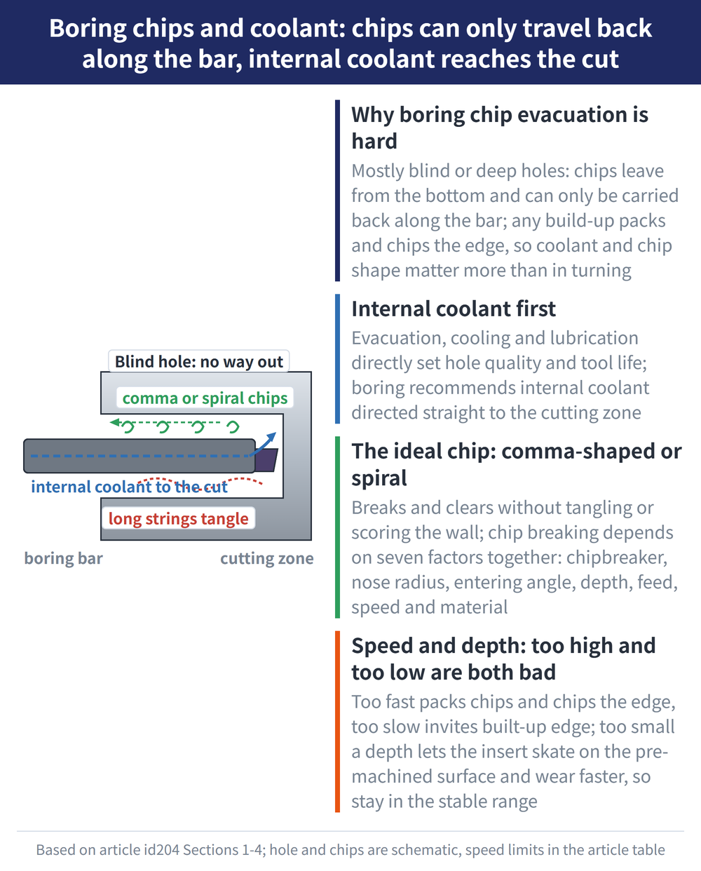
Boring is often into blind or deep holes, where chips must travel back out from the bottom, making evacuation harder than in turning — one of boring's core problems. This guide covers coolant supply (why internal comes first), the ideal chip shape (comma or spiral), cutting speed and depth of cut, plus tool maintenance and reaming practice.
1. Why boring chip evacuation is hard
Chip formation and evacuation are the key problem in boring, especially in blind holes — chips can only be carried back along the bar, so any build-up packs and chips the edge, making boring more demanding of coolant and chip shape than turning. For the four boring methods, see boring basics: four boring methods and the rigidity-first rule.
2. Coolant and chip shape
Coolant's main functions are to evacuate chips, cool and lubricate, directly affecting hole quality and tool life; boring recommends internal coolant, directed straight to the cutting zone. The ideal chip should be comma-shaped or spiral — breaking and clearing well without tangling the tool or scoring the wall. See Cutting Fluid Selection: Water-Miscible, Neat Oil, MQL and Dry for details.
Chip breaking depends on seven factors acting together: insert micro and macro geometry, nose radius, entering angle (lead angle), depth of cut, feed, cutting speed and material — tune them together.
3. Cutting speed: too high and too low are both bad
Too high risks poor evacuation, packing and edge chipping (especially in deep holes); too low invites built-up edge, worsening the finish, raising cutting force and shortening tool life. Below are the manufacturer's maximum initial cutting speeds by case as a starting reference:
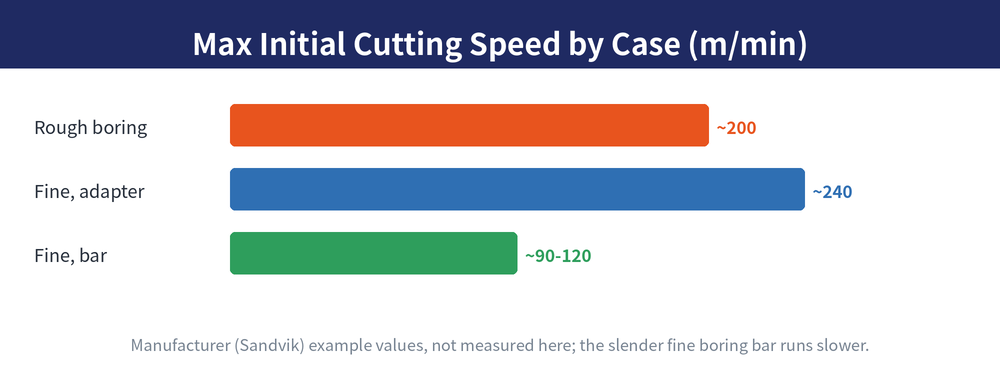
| Boring case | Max initial cutting speed vc |
|---|---|
| Rough boring | about 200 m/min |
| Fine boring with a fine boring adapter | about 240 m/min |
| Fine boring with a fine boring bar | about 90–120 m/min |
The adapter and the bar differ by more than double, because of rigidity: an adapter is short and stout and can run faster; a slender fine boring bar has long overhang and must run slower to control vibration. Cutting speed is mainly limited by vibration tendency, chip evacuation and long overhang. For actual values, use the hole-making formula guide: vc, spindle speed, feed and cycle time.
4. Feed and depth of cut: too small is also bad
Smaller is not safer: a large depth or too high a feed causes excessive edge engagement, vibration and higher power draw; but too small a depth lets the insert skate on the pre-machined surface, scoring it and accelerating wear. Depth must land in the range where the insert cuts stably. For shop-problem countermeasures, see boring troubleshooting: vibration, chips, feed marks and power.
5. Tool maintenance: don't let a small thing ruin the whole tool
Boring tool maintenance has a few principles that seem trivial but cost dearly:
| Maintenance point | Note |
|---|---|
| Use a torque wrench on screws | When fitting inserts and tools, always tighten to the recommended torque, not by feel |
| Clean and inspect regularly | Check inserts and seats are free of dust and undamaged; clean all parts before assembly |
| Lubricate periodically | At least once a year, oil all assembled parts and the fine boring adjustment mechanism |
| Never clamp a dampened tool's body | A dampened adapter is thin-walled; clamping the bar body crushes the damping mechanism and disables it |
| Check the spindle | Check the machine spindle runout, wear and clamping force |
Of these, "never clamp a dampened tool on the body" is the most overlooked yet costliest — it makes a dampened bar useless. For the full principles of dampened tools and overhang, see fine boring and tool overhang: single-edge tools and five principles.
6. Reaming practice
If the last pass is a reamer: a reamer can only correct hole diameter, not position or straightness error; the pre-machined hole's straightness error should be under 0.05mm; runout is critical, with a recommended maximum of 5μm; and ensure the reamer is concentric and choose the shortest possible holder and bar. On coolant, reaming clearly prefers emulsion over straight oil for longer tool life.
The cutting speed limits (rough boring about 200, fine boring adapter about 240, fine boring bar about 90–120 m/min), the 0.05mm reaming straightness and the 5μm runout are manufacturer (Sandvik) handbook examples/recommendations, not measurements by this site; follow the manufacturer's specifications and trial cuts.
Last updated: 2026-07-26
7. Frequently Asked Questions (FAQ)
Q: Should boring use internal or external coolant?
Internal first, directed straight to the cutting zone; boring is often into blind or deep holes where chips only carry back along the bar and external spray struggles to reach the bottom. The ideal chip shape is comma-shaped or spiral, breaking and clearing well without tangling or scoring.
Q: Is a lower cutting speed always safer in boring?
No — both too high and too low cause problems: too high risks packing and edge chipping, too low invites built-up edge. Starting reference: rough boring about 200 m/min, fine boring with an adapter about 240 m/min, fine boring with a bar about 90 to 120 m/min; a slender bar must run slower to control vibration.
Q: Does a smaller depth of cut give a better finish in boring?
No — too small a depth lets the insert skate on the pre-machined surface, scoring it and accelerating wear. Depth must land in the range where the insert cuts stably, the same phenomenon as "a too-shallow finishing pass vibrates more."
Q: What should I watch when using a reamer for the last pass?
A reamer can only correct hole diameter, not position or straightness error. The pre-machined hole's straightness should be under 0.05mm with a maximum runout of 5μm; ensure concentricity and choose the shortest holder and bar; reaming prefers emulsion over straight oil.
For the full reading guides on this topic, see Insert Selection: A Complete Reading Guide, Chip Control: A Complete Reading Guide and Vibration and Chatter: A Complete Reading Guide.









