
Milling Entry, Exit and Engagement: The Hidden Cause of Chipping
Chipping is usually blamed on a brittle insert, but the real cause is normally how the edge first touches the workpiece. This guide covers the engagement angle (the angular range over which the cutter is actually in contact with the workpiece), where the cutter centre should sit, and the difference between climb and conventional milling.
1. Chipping Is Blamed on Brittle Inserts, but the Problem Is the First Contact
Milling is an interrupted cut. Every tooth has to enter the workpiece once and leave it once per revolution, so the insert carries a train of impacts rather than a steady load.
Where that impact lands on the edge decides whether the insert holds or chips. It can be changed with the program and the setup position alone, so it costs nothing — yet it is the item most often overlooked.
When the cutting data is right and chipping still appears at random, check the entry and exit position before suspecting the insert grade. For the other failure patterns, see the Face Milling Troubleshooting Guide.
2. The Key to Entry: Make the Impact Land on the Strong Part of the Edge
The nose corner is the thinnest part of the whole edge. A good entry lets a thicker, better-supported part of the insert touch the material first, with the corner entering last.
The worst case is the corner hitting first, which concentrates the entire impact on the weakest single point. In practice this is controlled by the position of the cutter centre relative to the workpiece.
Whether the chip thickness (the thickness of the layer each edge actually removes) is large or small at the moment of entry is decided by that same positional relationship. How much impact the edge itself can absorb depends on its geometry, covered in the Face Milling Geometry Guide.
3. Three Ways to Position the Cutter Centre
The position of the cutter centre relative to the workpiece directly decides where the impact lands and how smooth the exit is.
| Centre position | At entry | At exit | Verdict |
|---|---|---|---|
| Inside the workpiece width (offset) | A thicker part of the insert contacts first; chip thickness runs from thick to thin | Smooth release, low impact | The recommended practice for face milling |
| On the workpiece centre line (centred) | Entry and exit are symmetrical, the impact lands mid-edge | Chip thickness is not zero, so the impact is higher | Workable but not optimal |
| Outside the workpiece | The thickest point lands on the weakest point of the edge | The engagement angle is short and the load swings sharply | Highest chipping risk |
| Cutter diameter versus workpiece width | A slightly larger cutter diameter is what leaves room for an offset | When the diameter is too small, a poor entry is hard to avoid | Consider it together when selecting the cutter |
The table gives general direction only; follow the catalogue or the relevant standard — not measurements taken by this site. No universal figure is given for the offset amount; for cutter selection considerations see the Face Milling Tool Selection Guide.
4. Manufacturer Reference: Chip Thickness Formulas for Five Cutter Positions
Manufacturer reference: the average and maximum chip thickness for the different cutter positions in 90° face milling are shown below.
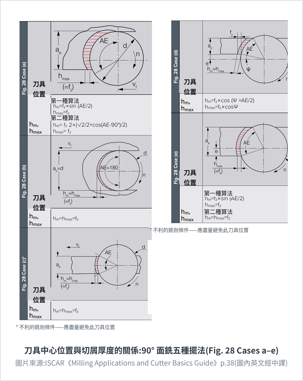
| Case | Cutter position (per the original figure geometry) | Average chip thickness hm | Maximum chip thickness hmax |
|---|---|---|---|
| Fig. 28 (a) | Cutter offset to one side of the workpiece, AE<180° | Method 1: hm=fz×sin(AE/2); Method 2: hm=fz·2×(√2/2+cos(AE−90°)/2) | hmax=fz |
| Fig. 28 (b) | On the centre line, ae=d, AE=180° (full engagement) | hm=hmax=fz | hmax=fz |
| Fig. 28 (c)* | Cutter centre outside the workpiece (edge engagement; unfavourable, should be avoided) | hm=hmax=fz | hmax=fz |
| Fig. 28 (d) | Cutter offset and with an entering angle Ψ | hm=fz×cos(Ψ+AE/2) | hmax=fz×cosΨ |
| Fig. 28 (e) | Cutter offset to the other side | Method 1: hm=fz×sin(AE/2); Method 2: hm=hmax=fz | hmax=fz |
Source: ISCAR, Milling Applications and Cutter Basics Guide, p.38 Table 3 / Fig. 28 (the figure reproduced here carries Chinese labels translated from the English original). fz = feed per tooth, AE = engagement angle, Ψ = entering angle, ae = radial depth of cut, d = cutter diameter. * marks an unfavourable cutter position that should be avoided.
5. Climb and Conventional Milling: The Impact Lands at Opposite Ends
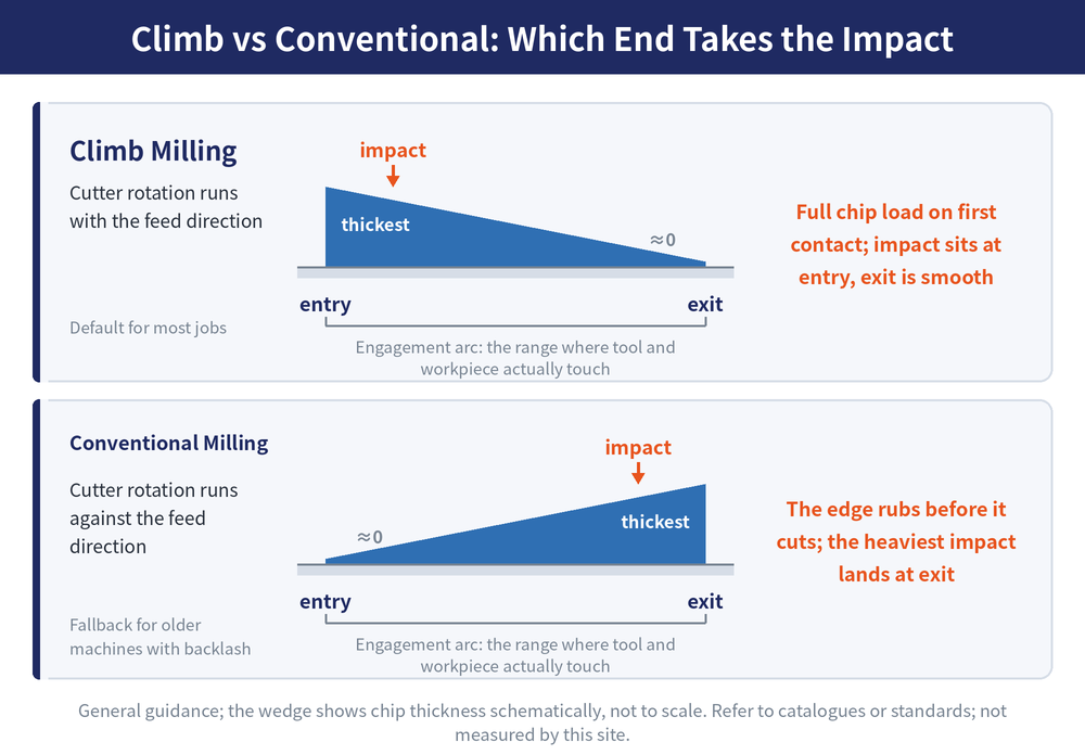
Climb milling (cutting edge rotation in the same direction as the feed) enters thick and exits thin; conventional milling (rotation opposing the feed) is the reverse. For the difference in selection see Climb Milling vs Conventional Milling.
| Criterion | Climb milling | Conventional milling |
|---|---|---|
| Chip thickness at entry | Maximum, full load on contact | Close to zero |
| Chip thickness at exit | Close to zero, smooth release | Maximum, hard release |
| What the edge does first | Cuts straight in | Rubs and slides before it starts cutting |
| Main side effect | The cutter pulls the table on a machine with backlash | Work hardening of the surface and faster edge wear |
| Positioning | The default in most cases | The fallback on older machines or where backlash exists |
The table gives general direction only; follow the catalogue or the relevant standard — not measurements taken by this site.
6. Countermeasures, Part 1: Setup, Edge and Feed
The countermeasures do not need a new machine; start with the program and the setup. The first three deal with the size of the impact and where it lands.
| Countermeasure | How to do it | Why it works |
|---|---|---|
| Adjust the cutter centre position | Move the centre off the workpiece centre line so that it sits inside the workpiece width | Shifts the impact from the nose corner to a strong part of the edge |
| Choose a tougher insert and a larger edge chamfer | Increase the edge chamfer and move toward a tougher grade | Thickens the edge cross-section so it can take the impact |
| Reduce the feed over the entry and exit zone | Drop F only over the short lead-in and lead-out segments | Impact scales with the feed |
The edge chamfer is a small land or radius deliberately ground on the cutting edge to reinforce it.
7. Countermeasures, Part 2: Toolpath and Vibration
The last three deal with the layout of the toolpath and with factors outside the cut itself.
| Countermeasure | How to do it | Why it works |
|---|---|---|
| Avoid leading out at the edge of a hole or slot | Shift the path so the cutter does not leave the cut at an edge | Those edges have no material behind them, so they chip easily and leave a burr |
| Replace a straight plunge-in with an arc lead-in | Program a circular path into the workpiece | Chip thickness builds up from zero |
| Check vibration and clamping at the same time | Chipping and chatter often appear together | Vibration amplifies the impact a second time |
For identifying and dealing with chatter, see Milling Chatter: Causes and Solutions; for where each milling method sits, see the Milling Methods Overview; for converting chip thickness, see Chip Thinning and Feed Compensation.
Last updated: 2026-08-08
8. Frequently Asked Questions (FAQ)
Q: Isn't centring the cutter on the workpiece the most intuitive setup?
Centring makes entry and exit symmetrical, but chip thickness is not zero at the moment of exit, so the impact is higher. Face milling is generally set up with the centre offset to inside the workpiece width.
Q: Why is a cutter centre outside the workpiece the worst case for chipping?
In that position the point of maximum chip thickness coincides with the weakest contact point on the edge, so the first impact lands straight on the nose corner. Changing the setup position, or using a cutter slightly larger in diameter, avoids it.
Q: Does programming an arc lead-in really help?
Yes. An arc path lets the chip thickness build up from zero and avoids an instantaneous collision, which shows most clearly on thin edge preparations and difficult-to-cut material.
Q: How much should the feed be reduced over the entry and exit zone?
There is no universal figure; decide it from the catalogue recommendation and an actual trial cut. The principle is to reduce it only over the short lead-in and lead-out segments.
For the full reading guides on this topic, see Tool Life and Wear: A Complete Reading Guide, Insert Selection: A Complete Reading Guide and Vibration and Chatter: A Complete Reading Guide.
This article is part of Milling Toolpaths: The Complete Guide - Roughing Strategy, Where to Plunge, and Choosing a Finishing Pattern; that guide shows how the whole topic fits together.









