
How to Improve Hole Accuracy: IT Tolerances and the Drill / Ream / Bore Route
A drawing says Ø15 H10, but the shop floor decides which operation opens the hole, whether a second one brings the tolerance in, and what gauge signs it off. Hole accuracy is the combination of nominal value, tolerance range and tolerance position, delivered as a relay between drilling, reaming or boring, and tapping.
1. Reading a Hole Tolerance: Three Independent Parameters
A hole dimension is defined by three parameters: the nominal value, the tolerance range (expressed as an ISO IT grade), and the tolerance position (upper case for holes, lower case for shafts).
Example: Ø15.00mm H10
Nominal value = 15.00mm; tolerance range = 0.07mm (IT10 to ISO); tolerance position = above zero (H to ISO, meaning the hole may only be equal to or larger than nominal).
Tolerance width is the difference between the maximum and minimum permissible sizes; the larger the IT number the wider it is. Hole grades A–H are positive and shaft grades a–h negative, paired by case (an H7 hole with an h7 shaft); fits fall into clearance, interference and transition. For figures, see Hole Tolerance Chart and Tolerance Grades and Fits Explained.
2. The Same IT Grade Means Different Widths at Different Diameters
IT10 is not a fixed number: the same grade gives a different actual width in each nominal size range, so the band always has to be looked up.
| Nominal size range | IT10 tolerance width | IT12 tolerance width |
|---|---|---|
| 6–10mm | 0.058mm | 0.15mm |
| 10–18mm | 0.07mm | 0.18mm |
Values are published ISO 286 / IT grade standard figures, not measurements taken by this site; see the standard for the complete matrix.
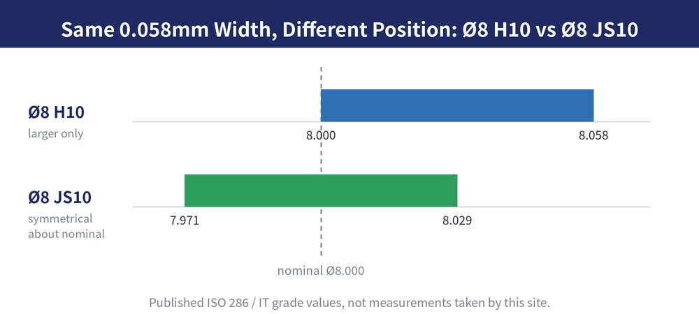
Put the same width in a different position and the acceptable range changes completely:
| Callout | Deviation | Acceptable hole diameter | Tolerance width |
|---|---|---|---|
| Ø8 H10 | +0.058 / 0 | 8.000 – 8.058mm | 0.058mm |
| Ø8 JS10 | ±0.029 | 7.971 – 8.029mm | 0.058mm |
Both are 0.058mm wide; only the position differs: aim H10 toward the plus side, hold JS10 to the centre.
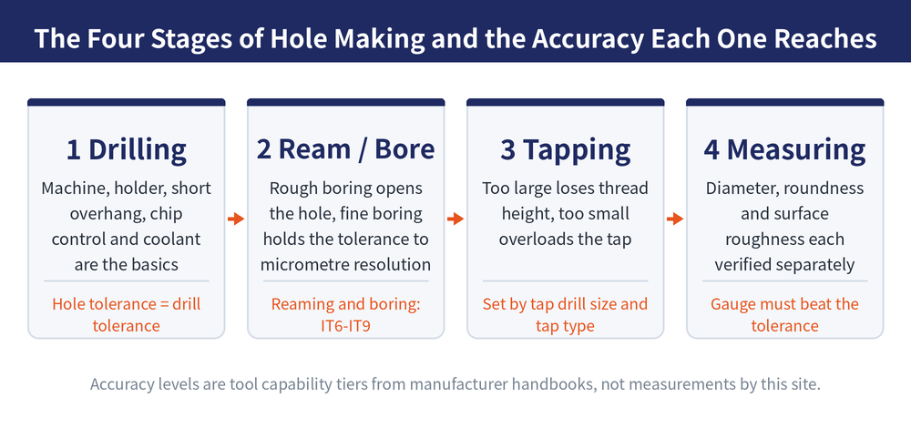
3. The Four Stages of Hole Making: One Overview Table
Each stage carries a different responsibility and accuracy level:
For the fuller set of process-chain combinations, see Machining Route Selection.
| Stage | Responsible for | Accuracy level | Common pitfall |
|---|---|---|---|
| 1. Drilling | Opening hole position and diameter | Close to the drill's own diameter tolerance (solid carbide, exchangeable-tip drills) | Excessive overhang, uncontrolled runout, poor chip evacuation |
| 2. Reaming / boring | Bringing it to target tolerance and position | Multi-edge rough boring, single-edge fine boring and multi-edge finishing reamers span IT6–IT9 | Radial deflection; adjusting after the tool is removed |
| 3. Tapping | Forming the internal thread | Tap drill size and tap type set thread height and fit class | Wrong tap drill size; runout causing an oversized internal thread |
| 4. Measurement | Checking diameter, roundness, roughness | Gauge resolution must beat the tolerance width or the reading proves nothing | Wrong contact type; temperature and feel drifting the reading |
Accuracy levels are taken from manufacturer technical handbooks, not measurements by this site; confirm against the catalogue and a trial cut.
4. Stage One — Drilling: The Tolerance Is Inherited from the Tool
Indexable insert drills stack seat and insert tolerance in two layers, but their plus-side holes match the H tolerance most holes carry, turning it into an advantage.
The most direct way to tighten this stage is drill presetting: trimming the effective cutting diameter on a lathe or with an adjustable holder or sleeve brings the tolerance range under 0.10mm; changing an insert's chipbreaker geometry also shifts the hole size of an indexable insert drill.
Repeatability rests on machine condition, holder quality, the shortest overhang, reliable chip breaking and evacuation, and coolant. Further reading: Straight Shank Drill Diameter and Runout, Hole Machining Formula Handbook, Deep Hole Drilling Guide, Drilling Troubleshooting Guide and Carbide Drill Regrinding Essentials.
5. Stage Two — Reaming and Boring: Bringing the Tolerance into IT6–IT9
When the drawing asks for more than drilling can hold, add another operation: a single-edge fine boring head presets the cutting edge to micrometre resolution and holds the tightest tolerances.
The mechanical problem is radial deflection (amplified by depth of cut and overhang), giving a smaller hole or vibration; the practical answer is reverse compensation:
Example: target hole Ø25mm H7
The tool cutting diameter is set to Ø25.021mm, 0.021mm above nominal.
The expected deflection is estimated in advance and the tool deliberately set larger, so the deflected result lands inside the tolerance band.
Make the final adjustment while the tool is still in the spindle, after measuring the hole (the reason is in the FAQ below). For boring bar selection, see Boring Bar Designation Explained.
6. Stage Three — Tapping: The Tap Drill Size Decides the Thread
Everything the first two stages achieved rides on the tap drill size: too large and thread height drops, too small and the tap is overloaded or breaks. Further reading: Metric Tap Drill Size Chart: M1–M100, Cutting Tap vs Forming Tap, Internal Thread Oversize and Drill and Tap Process Guide.
7. Surface Roughness Does Not Improve Automatically with Tolerance
A hole that measures in tolerance is not necessarily a good hole; roughness has its own drivers:
| Factor | How it acts |
|---|---|
| Chip formation of the material | P steel tends to long chips; M stainless is hard to control; K cast iron chips are brittle and break easily; N non-ferrous carries built-up edge and evacuation risk; S heat-resistant alloys resist cutting; H hardened steel gives short chips and easy evacuation |
| Feed | The higher the feed, the thicker the layer removed per revolution and the worse the roughness; cutting it lengthens cycle time |
| Cutting speed | Non-linear: a certain speed window generates built-up edge, worsening roughness and work hardening the surface; raise the speed further and built-up edge disappears, chips flow smoothly and micro-roughness improves |
| Rigidity of the technological system | Machine, tool and workpiece form a closed loop; insufficient rigidity leads straight to vibration |
| Drill geometry | Main cutting edge geometry shapes the force distribution; flute geometry governs evacuation, and trapped chips scratch the finished wall |
| Coolant | Promotes chip formation and evacuation, removes heat from the cutting zone and lubricates the friction surfaces (dry, oil-based, emulsion or MQL, minimum-quantity lubrication) |
Ra ranges are in Surface Roughness by Process Chart, and the Ra vs Rz difference in Surface Roughness Ra, Rz and RzJIS Explained.
8. Choosing the Route: Is an Extra Operation Justified?
Selection starts from diameter, depth and quality requirement (tolerance, surface finish, straightness), then a check on whether the hole conditions complicate the process (inclined faces, cross holes, extensions). Three approaches to stepped or chamfered holes:
| Method | Advantages | Disadvantages |
|---|---|---|
| Conventional drilling | Simple standard tools, relatively flexible | Stepped or chamfered holes need extra tools and operations |
| Step / chamfer drilling | Fewest operations; the fastest way to produce stepped or chamfered holes | Demands more power and stability, and is less flexible |
| Helical interpolation milling | Simple standard tools, highly flexible, low cutting forces | Longer production cycle |
The trade-offs listed are taken from manufacturer technical handbooks, not from measurements by this site; evaluate the choice together with machine power, clamping rigidity and batch size.
It only counts if it can be measured: contact types, readings and common errors are in Internal Diameter Measurement Guide.
Last updated: 2026-08-08
9. Frequently Asked Questions (FAQ)
Q: For a tight hole tolerance, should I ream or bore?
Both sit in IT6 to IT9: a reamer is fixed-size, one per hole size, suiting repeat production of the same diameter; a single-edge fine boring head adjusts to micrometre resolution, suiting high-mix low-volume or tight tolerances. When the position must also be pulled straight, choose boring — a reamer follows the existing hole and corrects position only slightly.
Q: Can drilling alone hold the tolerance on the drawing?
With modern solid carbide and exchangeable-tip drills hole tolerance is very close to drill tolerance, and presetting brings the range under 0.10mm. Where the drawing demands more, or position and roundness are specified too, reaming or boring belongs in the process.
Q: H10 and JS10 have the same tolerance width — can they be treated the same way?
No. At Ø8, H10 accepts 8.000–8.058mm and JS10 accepts 7.971–8.029mm — both 0.058mm wide but positioned differently (JS10 only 0.029mm each side). H10 can be aimed to the plus side to leave room for wear; JS10 must be held to the centre, and treating it as H scraps the batch once the diameter falls below nominal.
Q: After measuring a fine-bored hole, why can't the tool be removed before adjusting?
The deviation measured belongs to that set-up, so make the final adjustment while the tool is still in the spindle to compensate for spindle-to-tool deviation, radial deflection and insert wear together. Once removed and refitted the relationship may have shifted and the correction becomes a guess, so a trial cut after the final adjustment remains normal practice.
For the full reading guides on this topic, see Surface Finish: A Complete Reading Guide and Hole Accuracy: A Complete Reading Guide.
This article is part of Drill Bits: The Complete Guide - Start From Depth-to-Diameter, Then Pick the Drill and Set the Conditions; that guide shows how the whole topic fits together.









